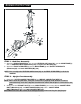
CE-3.0DS Owners’ Manual WARNING Exercise can present a health risk. Consult a physician before beginning any exercise program with this equipment. If you feel faint or dizzy, immediately discontinue use of this equipment. Serious bodily injury can occur if this equipment is not assembled and used correctly. Serious bodily injury can also occur if all instructions are not followed. Keep children and pets away from equipment. Always make sure all bolts and nuts are tightened prior to each use.
SAFETY INSTRUCTIONS WARNING: To reduce the risk of serious injury, read the following Safety Instructions before using CE-3.0DS. 1. Read all warnings posted on the equipment 2. Read this Owner's Manual and follow it carefully before using the equipment. Make sure that it is properly assembled and tightened before use 3. We recommend that two people be available for assembly of this product 4. Keep children and pets away from the equipment. Do not allow children and pets to use or play on the equipment .
“BEFORE YOU BEGIN” Thank you for choosing the CE-3.0DS. We take great pride in producing this quality product and hope it will provide many hours of quality exercise to make you feel better, look better and enjoy life to its fullest. Yes, it's a proven fact that a regular exercise program can improve your physical and mental health. Too often, our busy lifestyles limit our time and opportunity to exercise.
“HARDWARE IDENTIFICATION CHART” Unpack the box in a clear area. Use the List of Hardware below to check the contents of the hardware kit. This chart is provided to help identify the hardware used in the assembly process. Place the washers, the end of bolts, or screws on the circles to check for the correct diameter. Use the ruler to check the length of the bolts and screws.
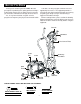
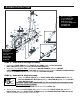
“ASSEMBLY INSTRUCTIONS” STEP 1 –Stabilizer Assembly a. Attach the REAR STABILIZER(2), the one with LEVELING CAP 76mm(76), onto the MAIN FRAME(1) with 2 x CARRIAGE BOLTS(M8x85mm)(104) and Nylon lock Nut (M8)(105). b. Attach the FRONT STABILIZER(3) onto the MAIN FRAME(1) with SOCKET HEAD BOLTS (M8x90mm)(94) and LOCK WASHERS(M8)(108). NOTE: You can adjust the LEVELING CAPS 76mm(76) on the REAR STABILIZER(2) to level the machine. STEP 2 – Upright Post Assembly a.
“ASSEMBLY INSTRUCTIONS” Prior to assembling check that Bolt (100) properly fits through Shaft Sleeve (54) located on the Right and Left Pedal Arm Assembly (14). NOTE: Part (15) must have the rectangular portion facing the rear of the machine when installing the pedal arm STEP 3 – Pedal Arm & Linkage Assembly a. Connect the PEDAL ARM(14) to the RIGHT Action ARM(12) with 1 x BUTTON HEAD BOLTS(M8x90mm)(100) and 1 x NYLON LOCK NUTS(M8)(105). b. Refer to the inset drawing (FIG.1).
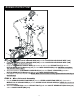
“ASSEMBLY INSTRUCTIONS” STEP 5 – Wire & Stationary Handlebar Assembly a. Connect the MIDDLE PULSE SENSOR WIRE(41A) and the LOWER PULSE SENSOR WIRE (42A). b. Connect the MIDDLE PULSE SENSOR WIRE(41B) and the LOWER PULSE SENSOR WIRE (42B). NOTE: Be careful not to pinch the wires c. Insert the STATIONARY HANDLE BAR(7,8) into the top tube on the UPRIGHT POST(4) with 2 x BUTTON HEAD BOLTS(M6x12mm)(114) and 2 x LOCK WASHERS(M6)(117). NOTE Do not tighten 114 until the end of step 5. d.
“ASSEMBLY INSTRUCTIONS” STEP 7 – Handlebar Assembly a. There is an “R” decal on the RIGHT HANDLEBAR(10) and an “L” decal on the LEFT HANDLEBAR(9). Slide the HANDLEBAR SLEEVE(48) onto the RIGHT HANDLEBAR(10). b. Attach the RIGHT HANDLEBAR(10) into the RIGHT PIVOTING ARM(12) with 2 x SOCKET HEAD BOLTS(M6x35mm)(90) and 2 x NYLON LOCK NUTS(M6)(102).NOTE: Assemble the SOCKET HEAD BOLTS(M6x35mm)(90) by following the direction as shown by the drawing c.
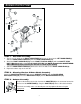
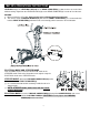
“SET UP & OPERATIONAL INSTRUCTIONS” LEVELING: Adjust the LEVELING CAPS(76) on the REAR STABILIZER(2) so that the item sets on the floor without rocking. Reposition the LEVELING CAPS(76) on the REAR STABILIZER(2) in order to level the item. MOVING: a. Before moving the CE-3.0DS, Make sure the unit is in Elliptical Mode Pictured below. b. The unit has a pair of MOVING WHEELS(75) built into the FRONT STABILIZER(3).
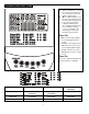
“CONSOLE INSTRUCTIONS” Take a few minutes to review the console layout. Below is an overview of the console’s features and functions We recommend that you use the console to help vary your workout routine and keep you focused on your progress toward your fitness goals. The computer programs and user feedback is a great source of motivation often assisting you to take your workout to the next level Power ON a. Make sure the item’s adaptor is correctly plugged into the socket b.
“CONSOLE INSTRUCTIONS – CONSOLE BUTTONS ” Console Buttons a. Press START/PAUSE to begin your exercise b. Press START/PAUSE again to stop and pause all functions during your exercise program. All the data on the display will then freeze. c. Press START/PAUSE again to resume the program and all the data displayed will continue until the program has finished. d.
“CONSOLE INSTRUCTIONS – CONSOLE BUTTONS ” During workout (after pressing START/PAUSE), pressing the mode button will scroll between Speed/Distance/Calories or RPM/ODO/Watts RPM, ODO, WATT will be displayed simultaneously SPEED, DISTANCE, CAL will be displayed simultaneously DISTANCE and ODO (ODOMETER) information: DISTANCE: a. This measures the total distance from 0 to 999 km/Mile. b. After pressing START/PAUSE, DISTANCE will count up.
“CONSOLE INSTRUCTIONS”– CONSOLE FUNCTIONS” Console Functions PROGRAM: The console comes with 16 preset programs Displays programs from P1 ~ P16 during set up Displays the selected program during exercise LEVEL: Displays resistance level of the current program, from 1 to 16 resistance levels in 1 level increments TIME: Count Up: If a target time was not selected, TIME will count up from 0:00 to maximum 99:59 minutes Count Down: If you have set the target time, the console will count d
“CONSOLE INSTRUCTIONS”– CONSOLE FUNCTIONS” CALORIES: Count Up: If target calories were not selected, this measures total calories your body burned during exercise Count Down: If you have set the preference value of calories, the console will count down from that selected target calories down to 0 BMR: (calculations are estimated) During BODY FAT TEST, the result would display the value of BMR in BODY FAT PROGRAM (P8) BMR (BASAL METABOLIC RATE) is a rate at which the body burns calories to mai
“CONSOLE INSTRUCTIONS – MANUAL PROGRAM (P1)” “1” Press any button on the console or begin pedaling to turn on the console a. Make sure that the power cord is properly plugged into the socket. b. The console would automatically shut off after 4 minutes of inactivity c. Press any button on the console or begin pedaling to turn on the console.
“CONSOLE INSTRUCTIONS – MANUAL PROGRAM (P1)” “B. SET TIME or DISTANCE To avoid confusion the user can only set time or distance in any one program. TO ENTER TIME: TO ENTER DISTANCE: UP or DOWN button: ENTER button and then UP or DOWN button: a. After entering the MANUAL PROGRAM (P1), the a. After entering the MANUAL PROGRAM (P1), the TIME function mode will appear with the display TIME function mode will appear with the display flashing “0:00”. flashing “0:00”. b.
“CONSOLE INSTRUCTIONS – MANUAL PROGRAM (P1)” 2. Age Selection: a. Press ENTER button to confirm the CALORIES value and enter the mode to set the AGE b. Use UP or DOWN buttons to set your AGE. Press ENTER to confirm (10 TO 99 YEARS OLD; 1 YEAR OLD INCREMENT) NOTE for AGE: NOTE: Although the console allows input for age beginning at 10 years old, the product is not recommended for use by children “D. START EXERCISE” Press START/ PAUSE to begin exercise. “START” would then appear on the screen “ E.
“CONSOLE INSTRUCTIONS – MANUAL PROGRAM (P1)” G. TARGET HEART RATE” The target heart rate is based on the Age that is set into the computer during setup. The TARGET HEART RATE calculation is based on 85% of the maximum heart rate. For example: For a 30-year-old user, the max. user heart rate should be 161 = (220-30) x 85% The console will monitor your pulse and compare the value of your pulse with TARGET HEART RATE.
“CONSOLE INSTRUCTIONS – PROGRAM (P2 ~ P7)” “1” Press any button on the console or begin pedaling to turn on the console d. Make sure that the power cord is properly plugged into the socket. e. The console would automatically shut off after 4 minutes of inactivity f. Press any button on the console or begin pedaling to turn on the console.
“CONSOLE INSTRUCTIONS – PROGRAM (P2 ~ P7)” “B. SET TIME or DISTANCE To avoid confusion the user can only set time or distance in any one program. c. TO ENTER TIME: TO ENTER DISTANCE: UP or DOWN button: ENTER button and then UP or DOWN button: After entering the P2~P7 the TIME function mode will a. After entering the P2~P7 the TIME function mode will appear with the display flashing “0:00”. appear with the display flashing “0:00”. d. Use UP or DOWN buttons to set the desired TIME b.
“CONSOLE INSTRUCTIONS – PROGRAM (P2 ~ P7)” “C. SET CALORIES and AGE” 1. Calories: a. After confirming the TIME or DISTANCE b. Use UP or DOWN buttons to set the desired CALORIES press enter to confirm (10 TO 9990KCAL; 10 KCAL INCREMENT) NOTE for CALORIES: Count Up: If target calories was not selected, this would measure total calories burned during exercise Count Down: If you have set the preference value of calories, the console will count down from that selected value down to 0 2. Age Selection: a.
“CONSOLE INSTRUCTIONS – PROGRAM (P2 ~ P7)” “F. CHANGING THE RESISTANCE LEVEL” Press the UP or DOWN button to change the resistance level (from 1 to 16 levels) at any time during the workout. . G. TARGET HEART RATE” The target heart rate is based on the Age that is set into the computer during setup. The TARGET HEART RATE calculation is based on 85% of the maximum heart rate. For example: For a 30-year-old user, the max.
“CONSOLE INSTRUCTIONS – BODY FAT PROGRAM (P8)” “A.“ENTER BODY FAT PROGRAM (P8)” a. START/PAUSE button: b. Press UP or DOWN button to select BODY FAT PROGRAM (P8) c. Press ENTER button to enter the BODY FAT PROGRAM (P8) “B. SET THE PERSONAL INFORMATION ( GENDER, HEIGHT and AGE )” After pressing the ENTER button, the GENDER mode will appear with the display flashing “ ”. Use UP or DOWN buttons to set your GENDER a. Press ENTER button to confirm your GENDER and enter the mode to set your HEIGHT b.
“CONSOLE INSTRUCTIONS – BODY FAT PROGRAM (P8)” “C. START TESTING YOUR BODY FAT” Press START/ PAUSE to start the test. The testing time takes about 10 seconds, please review the information below that corresponds to the test results. “D. THE BODY FAT RESULT INFORMATION” The illustration on the left is just an example to show you what the results should look like, each person has different body fat content depending on the user’s current health condition. 1.
“CONSOLE INSTRUCTIONS – BODY FAT PROGRAM (P8)” “D. THE BODY FAT RESULT INFORMATION” 4.
“CONSOLE INSTRUCTIONS – H. R. C. PROGRAM (P9 ~ P12)” T.H.R. 60% H.R.C. 75% H.R.C. 85% H.R.C. “3” H.R.C. PROGRAM (P9~P12) “A.“ENTER H.R.C. PROGRAM (P9~P12)” a. Press START/PAUSE button to activate the computer. b. Press UP or DOWN button to select H.R.C. PROGRAM (P9 ~ P12) PROGRAM (P9 ~ P12) c. Press ENTER button to confirm and enter H.R.C. d. Enter you Time or distance stated above “D.
“CONSOLE INSTRUCTIONS – H. R. C. PROGRAM (P9 ~ P12)” “ E. MUST-KNOWN HEART RATE PROGRAM INFO.” a. FORMULA OVERVIEW: BEGINNER: 60% of maximum heart rate; 60% of (220 – your age) TRAINER: 75% of maximum heart rate; 75% of (220 – your age) ACTIVE TRAINER: 85% of maximum heart rate; 85% of (220 – your age) b. Heart Rate Control Function The console will monitor your actual pulse and adjust the resistance level automatically to keep your pulse FIND YOUR TARGET HEART RATE within your TARGET HEART RATE ZONE.
“CONSOLE INSTRUCTIONS – H. R. C. PROGRAM (P9 ~ P12)” If you do not place your hands correctly, and a few seconds pass without a pulse input, the console will turn off the pulse circuit. The console will then display an error message “P”. Remove your hands from the sensor then replace your hands back on the Pulse Sensors correctly, the pulse readout will appear again “H.
“CONSOLE INSTRUCTIONS – USER SETTING PROGRAM (P13 ~ P16)” “A.“ENTER USER MODE PROGRAM (P13~P16)” a. Press START/PAUSE button to activate the computer b. Press UP or DOWN button to select USER MODE PROGRAM (P13 ~ P16) c. Press ENTER button to confirm and enter USER MODE PROGRAM (P13 ~ P16) “B. SET THE DESIRED TIME or DESIRED DISTANCE To avoid confusion the user can only set time or distance in any one program.
“CONSOLE INSTRUCTIONS – USER SETTING PROGRAM (P13 ~ P16)” TO ENTER TIME: TO ENTER DISTANCE: UP or DOWN button: ENTER button and then UP or DOWN button: e. After entering the User Program the TIME function a. mode will appear with the display flashing “0:00”. f. Use UP or DOWN buttons to set the desired TIME After entering the User Program the TIME function mode will appear with the display flashing “0:00”. b.
“CONSOLE INSTRUCTIONS – USER SETTING PROGRAM (P13 ~ P16)” “E. SET THE RESISTANCE LEVEL” : The USER SETTING PROGRAM allows the user to manually set the resistance level, the console will divide the time into 10 intervals. a. Enter the program to set the EACH TIME INTERVAL RESISTANCE LEVEL (1 TO 16 RESISTANCE LEVELS), then press ENTER button to confirm and move to the next interval b. Continue following the above process to finish setting the next 9 intervals. c.
“CONSOLE INSTRUCTIONS – USER SETTING PROGRAM (P13 ~ P16)” “H.CHANGING THE RESISTANCE” Press the UP or DOWN button to change the resistance level (from 1 to 16 levels) at any time during the workout. I. TARGET HEART RATE” The target heart rate is based on the Age that is set into the computer during setup. The TARGET HEART RATE calculation is based on 85% of the maximum heart rate. For example: For a 30-year-old user, the max.
“CONSOLE TROUBLE SHOOTING GUIDE“ PROBLEM E1 E2 E3 E5 POSSIBLE CAUSE SOLUTION 1. Motor Malfunction Replace Motor 2. Magnetic System Replace Magnetic System/Flywheel Malfunction or got stuck No Motor signal 3. Connection Wires are not Check whether the wires are well-connected or replace the well-connected or broken broke wires with the new wires 4. Console Malfunction Replace Console 1. Disconnect the Adaptor or Batteries. Reconnect the Adaptor or Batteries to REBOOT The Computer cannot the system.
“CONSOLE TROUBLE SHOOTING GUIDE“ PROBLEM POSSIBLE CAUSE SOLUTION Verify the gap between Speed Sensor and the Magnet is 5mm or less The Computer isn’t receiving a Verify that all the Wire Plugs are connected FIRMLY, correctly and are not signal from the Speed damaged The Speed Sensor? Verify that the sensor Magnet is installed correctly Display Show “O” The Sensor is faulty Replace the Speed Sensor The Computer is faulty Replace the Computer 1.
“CONDITIONING GUIDELINES” How you begin your exercise program depends on your physical condition. If you have been inactive for several years, or are severely overweight, you must slowly and increase your time on the item gradually: a few minutes per workout. Initially, you may be able to exercise only for a few minutes in your target zone, however, your aerobic fitness will improve over the next six to eight weeks. Don’t be discouraged if it takes longer. It’s important to work at your own pace.
“WARM-UP AND COOL-DOWN” Warm-up The purpose of warming up is to prepare your body for exercise and to minimize injuries. Warm up for two to five minutes before strength-training or aerobic exercising. Perform activities that raise your heart rate and warm the working muscles. Activities may include brisk walking, jogging, jumping jacks, jump rope, and running in place.
“PRODUCT PARTS DRAWING” 36
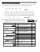
PARTS LIST NO. PART NAME QTY NO. PART NAME QTY CE-3.0-1 Main Frame 1 CE-3.0-42 Lower Pulse Sensor Wire 2 CE-3.0-2 Rear Stabilizer 1 CE-3.0-43 Linkage Connector 2 CE-3.0-3 Front Stabilizer 1 CE-3.0-44 Locking Knob 2 CE-3.0-4 Upright Post 1 CE-3.0-45 Connector 2 CE-3.0-5 Left AL Upright 1 CE-3.0-46 Console 1 CE-3.0-6 Right AL Upright 1 CE-3.0-47 Foam Grip 2 CE-3.0-7 Left Stationary Handlebar 1 CE-3.0-48 Handlebar Sleeve 2 CE-3.0-8 Right Stationary Handlebar 1 CE-3.
PARTS LIST NO. PART NAME QTY CE-3.0-84 Screw, M4x16mm 4 CE-3.0-85 Screw, M4x20mm 4 CE-3.0-86 Bolt, Round Head M5x12mm 2 CE-3.0-87 Screw, M5x10mm 4 CE-3.0-88 Screw, M5x20mm 4 CE-3.0-89 Screw, M6x10mm 8 CE-3.0-90 Bolt, Socket Head, M6x35mm 4 CE-3.0-91 Screw, M8x16mm 2 CE-3.0-92 Bolt, Socket Head M8x25mm 4 CE-3.0-94 Bolt, Socket Head M8x90mm 2 CE-3.0-95 Bolt, M8x16mm 4 CE-3.0-96 Bolt, M8x25mm 2 CE-3.0-97 Bolt, Round Head M8x16mm 8 CE-3.0-98 Bolt, M8x25mm 4 CE-3.
LIMITED HOME USE WARRANTY – SMOOTH FITNESS Ellipticals and DMTs Warranty Warranty Coverage: Smooth Fitness, Inc. ("Smooth Fitness") warrants to the original owner that each new product to be free from defects in workmanship and material, under normal use and conditions. Period of Coverage: The Warranty on this product runs from the date of original purchase using the following schedule: Model Name CE-3.