OPERATOR’S MANUAL BIG VAC Models 72-000-A Starting Serial # 72001 May, 2001 SMITHCO PRODUCT SUPPORT 1-800-891-9435 Hwy SS and Poplar Avenue, Cameron WI 54822 E-mail: productsupport@smithco.
Introduction CONTENTS Introduction ......................................... 1-10 Service Diagrams Introduction ............................................................................ 1-8 Introduction .............................................................................. 1 Symbols ................................................................................ 2-3 Safe Practices ......................................................................... 4 PTO Safety Warnings ..................
Thank you for purchasing a product. Read this manual and all other manuals pertaining to the Big Vac carefully as they contain safety, operating, assembly and maintenance instructions. Failure to do so could result in personal injury or equipment damage. Keep manuals in a safe place after operator and maintenance personnel have read them. Right and left sides are from the operator’s seat, facing forward. All machines have a Serial Number and Model Number. Both numbers are needed when ordering parts.
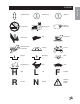
SYMBOLS Introduction 2 Read Operator’s Manual Electrical Power No Electrical Power Engine - Stop Engine - Start Engine - Run Engine Oil Temperature Light Water Temperature RPM Gasoline Diesel Glow Plug - On Glow Plug - Off Glow Plug Hour Meter Hour Meter Hand Throttle Choke - Closed Choke - Open Park Brake Park Brake Release Hydraulic Oil Level Off / Stop On / Start Fuse
H R Up/Down Arrow Down/Lower Up/Raise No Smoking Moving Parts Manual Operation Pinch Point Step Hot Surface Hydraulic Fluid Penetration Lift Arm Tractor Engage Disengage PTO Ground Speed Fast Slow High Reverse L N Low Neutral F Introduction SYMBOLS Forward Warning Danger Caution 3
SAFE PRACTICES Introduction 1. It is your responsibility to read this manual and all publications associated with this machine (engine, accessories and attachments). 2. Never allow anyone to operate or service the machine or its attachments without proper training and instructions. Never allow minors to operate any equipment. 3. Learn the proper use of the machine, the location and purpose of all the controls and gauges before you operate the equipment.
1. Always disengage the PTO, shut off engine and remove the keys before leaving the tractor seat. 2. Keep the tractor's master shield in place at all times. 3. Missing or damaged shielding is the main reason for driveline entanglement. Keep All Guards on and in good condition. Check guards frequently. 4. Never step across a rotating powershaft. Always walk around the revolving shaft even if guards are in place. 5. Dress for safety.
SPECIFICATIONS FOR BIG VAC Introduction WEIGHTS AND DIMENSIONS Length Width Height Weight 180" (458 cm) 84" (214 cm) 87" (221 cm) 3500 lb (1588 kg) SOUND LEVEL At Ear Level 92 dB (Use ear protection while operating) PTO SHAFT Maximum RPM 540 TIRES & WHEELS Two 26.5 - 1400 x 12 (18 psi (1.3 bar)) Fairway Type Turf Tires Castor: 6 x 12 (20 psi (1.4 bar)) FLUID CAPACITY Hydraulic Fluid Grade of Hydraulic Fluid 10 gallon (37.
The Big Vac arrives from 1. Introduction SETUP with some setup required. The PTO shaft and the rubber boot that goes around the blower and the reel need to be installed. 2. You will need a 40 HP (minimum) tow vehicle to remove the Big Vac from the trailer. a. Clevis Hitch - You will need a 3/4 diameter by 4" pin with some type of lock. b. Ball Hitch (optional) - You will need a 25/16" ball and a locking pin for the coupler. 3. Crank the jack on the Big Vac up so you can hook to tow vehicle. 4.
CONTROLS & INSTRUMENTS Introduction A. Hopper Lever - The hopper lever is used to lift and lower the hopper which also opens and closes the tailgate. Refer to decal for direction. B. Finger Reel Off-On Valve Turns the reel on or off. Refer to decal for direction. C. Deck Lift Lever - The deck lift lever is used to raise and lower the reel. Refer to decal for direction. D. Thatch Reel Off-On Valve Turns the reel on or off. Refer to decal for direction.
OPERATION Before operating this machine, become familiar with all controls and functions of this unit and the tow vehicle. Also complete all maintenance requirements and read all safety warnings. By knowing both machines thoroughly, how it operates and by doing the prescribed maintenance steps, you can expect relatively trouble-free operation for years to come. TOW VEHICLE You will need a 40 HP minimum tow vehicle. 1. Clevis Hitch - You will need a 3/4 diameter by 4" pin with some type of lock. Service 2.
HYDRAULIC DRAWING Diagrams 10
HYDRAULIC PARTS LIST 1 2 3 4 5 6 7 8 9 10 11 12* 13 14 15 16 17 18* 19 20 21 22 23 24 25 26 27 28 29 30 31* 32 * PART# DESCRIPTION 72-079 18-276 60-215 60-334 72-096 34-058 72-065 72-040 72-040-01 72-040-02 72-064 72-070 72-071 10-187 14-273 72-022 78-219-01 78-219-02 72-073 72-044 72-045 72-072 18-170 78-219 78-219-01 78-219-02 72-075 72-074 72-043 72-046 HRR-150 72-068 72-074 72-067 72-063 33-066 72-069 78-416 72-062 72-021 72-021-01 72-066 Suction Hose Tee Fitting 11/4 Filter Filter Element (repl
EC DECLARATION OF CONFORMITY according to Directive 89/392/EEC SMITHCO INC. We (Name of supplier) 34 West Ave.
LIMITED WARRANTY SMITHCO warrants this product to be free from defects in material and workmanship under normal use for one year from the date of purchase by the original user. (60 days if product is used for rental purposes.) All warranty claims must be handled through a SMITHCO authorized dealer or by SMITHCO, INC. All transportation charges must be paid by the purchaser. There is no further express warranty.