Contents 1.1 1.2 1.3 1.4 1.5 1.6 1.7 General safety instructions Manufacturer liability Appliance purpose Disposal Identification plate This user manual How to read the user manual 2 Description 2.1 2.2 2.3 2.4 2.5 General Description Cooking hob Control panel Other parts Available accessories 3 Use 3.1 3.2 3.3 3.4 3.5 3.6 3.
Instructions 1 Instructions 1.1 General safety instructions Risk of personal injury • During use the appliance and its accessible parts become very hot. • Never touch the heating elements during use. • Keep children under eight years of age at a safe distance if they are not constantly supervised. • Children must never play with the appliance. • Never rest metallic objects such as knives, forks, spoons and lids on the appliance during use. • Switch the appliance off immediately after use.
For this appliance 1.4 Disposal • Ensure that the appliance is switched off before replacing the bulb. • Do not rest any weight or sit on the open door of the appliance. • Take care that no objects are stuck in the doors. This appliance must be disposed of separately from other waste (Directives 2002/95/EC, 2002/ 96/EC, 2003/108/EC). The appliance does not contain substances in quantities sufficient to be considered hazardous to health and the environment, in accordance with current European directives.
Instructions Our appliances are packed in nonpolluting and recyclable materials. • Consign the packing materials to the appropriate selective collection centres. Plastic packaging Danger of suffocation • Do not leave the packaging or any part of it unattended. • Do not let children play with the packaging plastic bags. 1.5 Identification plate The identification plate bears the technical data, serial number and brand name of the appliance. Do not remove the identification plate for any reason. 1.
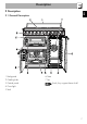
Description EN 2 Description 2.
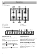
Description 2.2 Cooking hob AUX = Auxiliary SR = Semi-rapid R = Rapid UR = Ultra rapid 2.3 Control panel Hob burner knobs (1) Programmer clock (2) Useful for lighting and adjusting the hob burners. Press and turn the knobs anti-clockwise to the value to light the relative burners. Turn the knobs to the zone between the maximum and minimum setting to adjust the flame. Return the knobs to the position to turn off the burners.
Auxiliary oven variable grill indicator light (4) The indicator light comes on to indicate that the auxiliary oven is heating up. It turns off as soon as it reaches the set temperature. It flashes regularly to indicate that the temperature set inside the oven is kept constant. Lower multifunction oven temperature knob (5) This knob allows you to select the cooking temperature and the Vapor Clean temperature. Turn the knob clockwise to the required value, between the minimum and maximum setting.
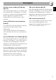
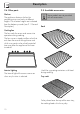
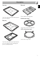
Description 2.4 Other parts 2.5 Available accessories Shelves The appliance features shelves for positioning trays and racks at different heights. The insertion heights are indicated from the bottom upwards (see 2.1 General Description). Some models are not provided with all accessories. Rack Cooling fan The fan cools the ovens and comes into operation during cooking.
Description Useful for collecting fat from foods placed on the rack above. Plate rack EN Oven tray To be used for warming plates. Reduction pan stand Deep tray Useful when using small cookware. WOK reduction pan stand Useful when using a wok. Useful for collecting fat from foods placed on the rack above and for cooking pies, pizzas and baked desserts.
Use 3 Use 3.1 Instructions High temperature inside the oven during use Danger of burns • Keep the oven door closed during cooking. • Protect your hands wearing heat resistant gloves when moving food inside the oven. • Do not touch the heating elements inside the oven. • Do not pour water directly onto very hot trays. • Do not allow children younger than 8 years old to come near the appliance when in operation.
Use • Do not cover the bottom of the oven cavity with aluminium or tin foil sheets. • If you wish to use greaseproof paper, place it so that it will not interfere with the hot air circulation inside the oven. • Do not place pans or trays directly on the bottom of the oven cavity. • Do not use the open door to rest pans or trays on the internal glass pane. • Do not pour water directly onto very hot trays.
Use Tray rack The tray rack has to be inserted into the tray. In this way fat can be collected separately from the food which is being cooked. Reduction pan stands The reduction pan stands have to be placed on the hob grids. Make sure they are properly placed. Plate rack 1. Insert the plate rack without plates in the first shelf of the side oven. 2. Position the plates as shown in the figure. 3. Heat the oven to a temperature no greater than 50°C for no more than 15 minutes. 4.
Use All the appliance's control and monitoring devices are located together on the front panel. The burner controlled by each knob is shown next to the knob. The appliance is equipped with an electronic ignition device. Simply press the knob and turn it anticlockwise to the maximum flame symbol, until the burner lights. If the burner does not light in the first 15 seconds, turn the knob to and wait 60 seconds before trying again.
Use 3.5 Using the ovens Switching on the auxiliary oven Switching on the multifunction oven To switch on the multifunction oven: 1. Select the cooking function using the function knob. 2. Select the temperature using the temperature knob. Opening and closing the doors of the multifunction/side ovens The multifunction and side ovens are equipped with a swing door. To open, pull the door handle towards you. To close, push the doors until you hear a mechanical “click”.
Functions list ECO Depending on the function it is combined with, this ensures the greatest possible energy savings during cooking. Static As the heat comes from above and below at the same time, this system is particularly suitable for certain types of food. Traditional cooking, also known as static cooking, is suitable for cooking just one dish at a time. Perfect for all types of roasts, bread and cakes and in any case particularly suitable for fatty meats such as goose and duck.
Use Fan + circulaire The combination of the fan and the circulaire heating element (incorporated in the rear of the oven) allows you to cook different foods on several levels, as long as they need the same temperatures and same type of cooking. Hot air circulation ensures instant and even distribution of heat. It will be possible, for instance, to cook fish, vegetables and biscuits simultaneously (on different levels) without odours and flavours mingling.
• Grilling processes should never last more than 60 minutes using multifunction ovens, 30 minutes inside the auxiliary oven. Advice for cooking desserts/pastries and biscuits • Use dark metal moulds: they help to absorb the heat better. • The temperature and the cooking time depend on the quality and consistency of the dough. • To check whether the dessert is cooked right through: at the end of the cooking time, put a toothpick into the highest point of the dessert.
Use 3.7 Programmer clock Setting the time On the first use, or after a power failure, the digits will be flashing on the appliance's display. 1. Press the and keys at the same time. The dot between the hours and the minutes flashes. 2. The time can be set using or . Keep the key pressed in to increase or decrease rapidly. 3. Press the key or wait 5 seconds. The dot between the hours and the minutes stops flashing.
4. At the end of cooking the heating elements will be deactivated. On the display, symbol turns off, symbol flashes and the buzzer sounds. 5. To turn off the buzzer just press any key of the programmer clock. 6. Press keys and at the same time to reset the programmer clock. It is not possible to set a cooking time of more than 10 hours. After the setting, to display the cooking time left press the key. symbols and will appear on the display. 5.
Use Minute minder timer Adjusting the buzzer volume The minute minder timer does not stop the cooking but rather informs the user when the set time has run out. The buzzer volume can be set to 3 different levels. When the buzzer is in operation, press to change the setting. The minute minder timer can be activated at any time. 1. Press key. The display will shows the Press keys and at the same time to reset the programs set. Then switch off the oven manually if cooking is in progress.
Use Food Lasagne Pasta bake Roast veal Pork loin Pork shoulder Roast rabbit Turkey breast Roast pork neck Roast chicken Weight (Kg) Function 3 2.
Cleaning and maintenance 4 Cleaning and maintenance 4.1 Instructions Improper use Risk of damage to surfaces • Do not use steam jets for cleaning the appliance. • Do not use cleaning products containing chlorine, ammonia or bleach on steel parts or parts with metallic finishes on the surface (e.g. anodizing, nickel- or chromium-plating). • Do not use abrasive or corrosive detergents on glass parts (e.g. powder products, stain removers and metallic sponges).
Cleaning and maintenance For easier cleaning, the flame-spreader crowns and the burner caps can be removed. Wash them in hot water and nonabrasive detergent. Carefully remove any encrustation, then wait until they are perfectly dry. Refit the flame-spreader crowns making sure that they are correctly positioned in their housings with their respective burner caps. 4.
Cleaning and maintenance 3. To reassemble the door, put the hinges in the relevant slots in the oven, making sure that grooved sections A are resting completely in the slots. Lower the door and once it is in place remove the pins from the holes in the hinges. 2. Then, pull the bottom part upwards (2). In this way, the 4 pins attached to the glass detach from their housings in the oven door. 4.4 Cleaning the door glazing 3.
4. Remove the intermediate glass pane. First raise it upwards (1) and then remove it pulling it downwards (2). 5. Clean the external glass pane and the panes previously removed. Use absorbent kitchen roll. In case of stubborn dirt, wash with a damp sponge and neutral detergent. 7. Reposition the internal glass pane. Take care to centre and insert the 4 pins into their housings in the oven door by applying slight pressure. Auxiliary oven door 1.
Cleaning and maintenance 3. Remove the intermediate glass pane by lifting it upwards. 4. Clean the external glass pane and the panes previously removed. Use absorbent kitchen roll. In case of stubborn dirt, wash with a damp sponge and neutral detergent. 4.6 Cleaning the inside of the oven For the best oven upkeep, clean it regularly after having allowed it to cool. Take out all removable parts. Clean the oven racks with warm water and non-abrasive detergent. Carefully rinse and dry damp parts.
Cleaning and maintenance Removing the guide frames enables the sides to be cleaned more easily. This operation should be performed each time the automatic cleaning cycle is used (on some models only). To remove the guide frames: Pull the frame towards the inside of the oven to unhook it from its groove A, then slide it out of the seats B at the back. When cleaning is complete, repeat the above procedures to put the guide frames back in. 4.
Cleaning and maintenance Vapor Clean setting 1. Turn the function knob to the • Spray a water and washing up liquid solution inside the oven using a spray nozzle. Direct the spray against the side walls, upwards, downwards and towards the deflector. • Close the door. We recommend spraying approx. 20 times at the most. symbol and the temperature knob to the symbol. 2. Set a cooking time of 18 minutes using the programmer clock. 3.
4.8 Extraordinary maintenance Live parts Danger of electrocution • Disconnect the oven power supply. 6. Refit the cover correctly, so that the moulded part of the glass is facing the door. 7. Press the cover completely down so that it attaches perfectly to the bulb support. Removing the seal of the auxiliary oven Replacing the internal light bulb 1. Completely remove all accessories from inside the oven. 2. Remove the racks/trays support frames. 3. Remove the bulb cover using a tool (e.g. a screwdriver).
Installation 5 Installation 5.1 Clearances above and around domestic appliances Requirements 1. Overhead clearances – (Measurement A) Range hoods and exhaust fans shall be installed in accordance with the manufacturer’s instructions. However, in no case shall the clearance between the highest part of the hob of the cooking appliance and a range hood be less than 600 mm or, for an overhead exhaust fan, 750 mm.
Installation Notes 1. Requirement 3 does not apply to a freestanding or elevated cooking appliance which is designed to prevent flames or the cooking vessels from extending beyond the periphery of the appliance. 2. The ‘cooking surface area’ is defined as that part of the appliance where cooking normally takes place and does not include those parts of the appliance containing control knobs. 3. For definition of hob, see Clause 1.4.64. 4. For definition of trivet, see Clause 1.4.109. 5.
Installation Connection of the appliance to the gas supply must be in accordance with the requirements of AS5601. A ½” BSP connector at the inlet is recommended and the gas supply line to the appliance must be of adequate length to allow sufficient withdrawal of appliance for service or disconnection and be: 1. annealed copper pipe or; 2. flexible hose according to AS/NZ1869 & be at least Class “B”, 10 mm diameter.
Room ventilation Combustion gas discharge The room containing the appliance should have a permanent air supply in accordance with the standards in force. The room where the appliance is installed must have enough air flow needed for the regular combustion of gas and the necessary air change in the room itself. The hob shall be installed in rooms with natural ventilation, as required by Standards regulations AS/NZS5601.
Installation 5.3 Adaptation to different types of gas The appliance is pre-set for natural gas at a pressure of 1.0 kPa. In case of operation with other types of gas, the burner nozzles must be changed and the minimum flame adjusted on the gas taps. Replacing nozzles 1. Remove the pan stands, burner caps and flame-spreader crowns to access the burner casings. 2. Replace the nozzles using a 7 mm spanner according to the gas to be used (see Burner and nozzle characteristics tables). 3.
Adjusting the minimum setting for LPG Lubrication of gas taps Tighten the screw located at the side of the tap rod clockwise all the way. Over time the gas taps may become difficult to turn and get blocked. Clean them internally and replace the lubrication grease. Following adjustment to a gas other than the one originally set in the factory, replace the gas setting label fixed to the appliance with the one corresponding to the new gas. The label is inserted inside the nozzle pack (where present).
Installation 5.4 Electrical connection Power voltage Danger of electrocution • Have the electrical connection performed by authorised technical personnel. • Use personal protective equipment. • The appliance must be connected to earth in compliance with electrical system safety standards. • Disconnect the main power supply. • Do not pull the cable to remove the plug. • Use H05V2V2-F cables withstanding a temperature of at least 90°C.
Installation Fit the power line with an omnipolar circuit breaker in compliance with installation regulations. The circuit breaker should be located near the appliance and in an easily reachable position. Connection with plug and socket Make sure that the plug and socket are of the same type. Avoid use of adapters and shunts as these could cause overheating and a risk of burns. Overall dimensions Location of gas and electrical connection points. 5.
Installation Assembling the skirt Mounting the toe skirt The backguard provided is an integral part of the product; it must be fastened to the appliance prior to installation. The toe skirt provided is an integral part of the product; it must be fastened to the appliance prior to installation. The backguard must always be positioned and secured correctly on the appliance. 1. Loosen the 6 screws on the back of the top (A) and unscrew the 2 screws (B) on the side part of the backguard.
Positioning and levelling the appliance Wall fixing After making the electrical and/or gas connections, properly level the appliance on the floor to ensure better stability. Screw or unscrew the bottom part of the foot until the appliance is stable and level on the floor. 1. Attach the chain to the cooker 2. Stretch out the chain attached to the cooker horizontally so that the other end touches the wall. 3. Mark the wall in the position where the hole is to be drilled. 4.