Contents 1.1 1.2 1.3 1.4 1.5 1.6 1.7 General safety instructions Manufacturer liability Appliance purpose Disposal Identification plate This user manual How to read the user manual 2 Description 2.1 2.2 2.3 2.4 2.5 General Description Cooking hob Control panel Other parts Available accessories 3 Use 3.1 3.2 3.3 3.4 3.5 3.6 3.
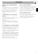
Instructions 1 Instructions 1.1 General safety instructions Risk of personal injury • During use the appliance and its accessible parts become very hot. • Never touch the heating elements during use. • Keep children under eight years of age at a safe distance if they are not constantly supervised. • Children must never play with the appliance. • Never rest metallic objects such as knives, forks, spoons and lids on the appliance during use. • Switch the appliance off immediately after use.
For this appliance 1.4 Disposal • Ensure that the appliance is switched off before replacing the bulb. • Do not rest any weight or sit on the open door of the appliance. • Take care that no objects are stuck in the doors. This appliance must be disposed of separately from other waste (Directives 2002/95/EC, 2002/ 96/EC, 2003/108/EC). The appliance does not contain substances in quantities sufficient to be considered hazardous to health and the environment, in accordance with current European directives.
Instructions Our appliances are packed in nonpolluting and recyclable materials. • Consign the packing materials to the appropriate selective collection centres. Plastic packaging Danger of suffocation • Do not leave the packaging or any part of it unattended. • Do not let children play with the packaging plastic bags. 1.5 Identification plate The identification plate bears the technical data, serial number and brand name of the appliance. Do not remove the identification plate for any reason. 1.
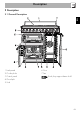
Description 2 Description EN 2.
Description 2.2 Cooking hob AUX = Auxiliary SR = Semi-rapid R = Rapid UR = Ultra rapid 2.3 Control panel Hob burner knobs (1) Programmer clock (2) Useful for lighting and adjusting the hob burners. Press and turn the knobs anti-clockwise to the value to light the relative burners. Turn the knobs to the zone between the maximum and minimum setting to adjust the flame. Return the knobs to the position to turn off the burners.
Description The indicator light comes on to indicate that the auxiliary oven is heating up. It turns off as soon as it reaches the set temperature. It flashes regularly to indicate that the temperature set inside the oven is kept constant. Lower multifunction oven temperature knob (5) This knob allows you to select the cooking temperature and the Vapor Clean temperature. Turn the knob clockwise to the required value, between the minimum and maximum setting.
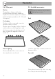
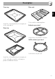
Description 2.4 Other parts 2.5 Available accessories Shelves The appliance features shelves for positioning trays and racks at different heights. The insertion heights are indicated from the bottom upwards (see 2.1 General Description). Some models are not provided with all accessories. Rack Cooling fan The fan cools the ovens and comes into operation during cooking.
Description Plate rack EN Oven tray Useful for collecting fat from foods placed on the rack above. To be used for warming plates. Reduction pan stand Deep tray Useful when using small cookware. WOK reduction pan stand Useful when using a wok. Useful for collecting fat from foods placed on the rack above and for cooking pies, pizzas and baked desserts.
Use 3 Use 3.1 Instructions High temperature inside the oven during use Danger of burns • Keep the oven door closed during cooking. • Protect your hands wearing heat resistant gloves when moving food inside the oven. • Do not touch the heating elements inside the oven. • Do not pour water directly onto very hot trays. • Do not allow children younger than 8 years old to come near the appliance when in operation.
Use • Do not cover the bottom of the oven cavity with aluminium or tin foil sheets. • If you wish to use greaseproof paper, place it so that it will not interfere with the hot air circulation inside the oven. • Do not place pans or trays directly on the bottom of the oven cavity. • Do not use the open door to rest pans or trays on the internal glass pane. • Do not pour water directly onto very hot trays.
Use Tray rack The tray rack has to be inserted into the tray. In this way fat can be collected separately from the food which is being cooked. Reduction pan stands The reduction pan stands have to be placed on the hob grids. Make sure they are properly placed. Plate rack 1. Insert the plate rack without plates in the first shelf of the side oven. 2. Position the plates as shown in the figure. 3. Heat the oven to a temperature no greater than 50°C for no more than 15 minutes. 4.
Use All the appliance's control and monitoring devices are located together on the front panel. The burner controlled by each knob is shown next to the knob. The appliance is equipped with an electronic ignition device. Simply press the knob and turn it anticlockwise to the maximum flame symbol, until the burner lights. If the burner does not light in the first 15 seconds, turn the knob to and wait 60 seconds before trying again.
Use 3.5 Using the ovens Switching on the auxiliary oven Switching on the multifunction oven To switch on the multifunction oven: 1. Select the cooking function using the function knob. 2. Select the temperature using the temperature knob. Opening and closing the doors of the multifunction/side ovens The multifunction and side ovens are equipped with a swing door. To open, pull the door handle towards you. To close, push the doors until you hear a mechanical “click”.
Functions list ECO Depending on the function it is combined with, this ensures the greatest possible energy savings during cooking. Static As the heat comes from above and below at the same time, this system is particularly suitable for certain types of food. Traditional cooking, also known as static cooking, is suitable for cooking just one dish at a time. Perfect for all types of roasts, bread and cakes and in any case particularly suitable for fatty meats such as goose and duck.
Use Fan + circulaire The combination of the fan and the circulaire heating element (incorporated in the rear of the oven) allows you to cook different foods on several levels, as long as they need the same temperatures and same type of cooking. Hot air circulation ensures instant and even distribution of heat. It will be possible, for instance, to cook fish, vegetables and biscuits simultaneously (on different levels) without odours and flavours mingling.
Use Advice for cooking desserts/pastries and biscuits • Use dark metal moulds: they help to absorb the heat better. • The temperature and the cooking time depend on the quality and consistency of the dough. • To check whether the dessert is cooked right through: at the end of the cooking time, put a toothpick into the highest point of the dessert. If the dough does not stick to the toothpick, the dessert is cooked.
Use 3.7 Programmer clock Setting the time On the first use, or after a power failure, the digits will be flashing on the appliance's display. 1. Press the and keys at the same time. The dot between the hours and the minutes flashes. 2. The time can be set using or . Keep the key pressed in to increase or decrease rapidly. 3. Press the key or wait 5 seconds. The dot between the hours and the minutes stops flashing.
4. At the end of cooking the heating elements will be deactivated. On the display, symbol turns off, symbol flashes and the buzzer sounds. 5. To turn off the buzzer just press any key of the programmer clock. 6. Press keys and at the same time to reset the programmer clock. It is not possible to set a cooking time of more than 10 hours. After the setting, to display the cooking time left press the key. To reset the set program, press keys and at the same time and switch off the oven manually. 4.
Use Minute minder timer Adjusting the buzzer volume The minute minder timer does not stop the cooking but rather informs the user when the set time has run out. The buzzer volume can be set to 3 different levels. When the buzzer is in operation, press to change the setting. The minute minder timer can be activated at any time. 1. Press key. The display will shows the Press keys and at the same time to reset the programs set. Then switch off the oven manually if cooking is in progress.
Use Cooking information table Lasagne Pasta bake Roast veal Pork loin Pork shoulder Roast rabbit Turkey breast Roast pork neck Roast chicken Temperature Static Static Runner position from the bottom 1 or 2 1 or 2 220 - 230 220 - 230 40 - 50 40 Circulaire Circulaire Fan assisted Circulaire Fan assisted Fan assisted Fan assisted 2 2 2 2 2 2 2 180 - 190 180 - 190 180 - 190 180 - 190 180 - 190 180 - 190 190 - 200 70 - 80 70 - 80 90 - 100 70 - 80 110 - 120 190 - 210 60 - 70 Weight (Kg) Function 3 2.
Cleaning and maintenance 4 Cleaning and maintenance 4.1 Instructions Improper use Risk of damage to surfaces • Do not use steam jets for cleaning the appliance. • Do not use cleaning products containing chlorine, ammonia or bleach on steel parts or parts with metallic finishes on the surface (e.g. anodizing, nickel- or chromium-plating). • Do not use abrasive or corrosive detergents on glass parts (e.g. powder products, stain removers and metallic sponges).
Cleaning and maintenance For easier cleaning, the flame-spreader crowns and the burner caps can be removed. Wash them in hot water and nonabrasive detergent. Carefully remove any encrustation, then wait until they are perfectly dry. Refit the flame-spreader crowns making sure that they are correctly positioned in their housings with their respective burner caps. 4.3 Removing the door of the auxiliary oven For easier cleaning, the door can be removed and placed on a canvas.
Cleaning and maintenance 3. To reassemble the door, put the hinges in the relevant slots in the oven, making sure that grooved sections A are resting completely in the slots. Lower the door and once it is in place remove the pins from the holes in the hinges. 2. Then, pull the bottom part upwards (2). In this way, the 4 pins attached to the glass detach from their housings in the oven door. 4.4 Cleaning the door glazing 3.
Cleaning and maintenance 7. Reposition the internal glass pane. Take care to centre and insert the 4 pins into their housings in the oven door by applying slight pressure. EN 4. Remove the intermediate glass pane. First raise it upwards (1) and then remove it pulling it downwards (2). 5. Clean the external glass pane and the panes previously removed. Use absorbent kitchen roll. In case of stubborn dirt, wash with a damp sponge and neutral detergent. Auxiliary oven door 1.
Cleaning and maintenance 3. Remove the intermediate glass pane by lifting it upwards. 4. Clean the external glass pane and the panes previously removed. Use absorbent kitchen roll. In case of stubborn dirt, wash with a damp sponge and neutral detergent. 4.6 Cleaning the inside of the oven For the best oven upkeep, clean it regularly after having allowed it to cool. Take out all removable parts. Clean the oven racks with warm water and non-abrasive detergent. Carefully rinse and dry damp parts.
Cleaning and maintenance Removing the guide frames enables the sides to be cleaned more easily. This operation should be performed each time the automatic cleaning cycle is used (on some models only). To remove the guide frames: Pull the frame towards the inside of the oven to unhook it from its groove A, then slide it out of the seats B at the back. When cleaning is complete, repeat the above procedures to put the guide frames back in. 4.
Cleaning and maintenance Vapor Clean setting 1. Turn the function knob to the • Spray a water and washing up liquid solution inside the oven using a spray nozzle. Direct the spray against the side walls, upwards, downwards and towards the deflector. • Close the door. We recommend spraying approx. 20 times at the most. symbol and the temperature knob to the symbol. 2. Set a cooking time of 18 minutes using the programmer clock. 3.
4.8 Extraordinary maintenance Live parts Danger of electrocution • Disconnect the oven power supply. 5. Replace the lamp with one of the same type (40W). 6. Refit the cover correctly, so that the moulded part of the glass is facing the door. 7. Press the cover completely down so that it attaches perfectly to the bulb support. Replacing the internal light bulb Removing the seal of the auxiliary oven 1. Completely remove all accessories from inside the oven. 2. Remove the racks/trays support frames. 3.
Installation 5 Installation 5.1 Gas connection Gas leak Danger of explosion • After carrying out any operation, check that the tightening torque of gas connections is between 10 Nm and 15 Nm. • If required, use a pressure regulator that complies with current regulations. • At the end of the installation, check for any leaks with a soapy solution, never with a flame.
Installation Connection with a flexible steel hose with bayonet fitting Carry out the connection to the gas mains using a flexible steel hose with bayonet fitting compliant with B.S. 669. Apply insulating material to the thread of the gas hose connector 4 and then tighten the adapter 3. Screw the assembly to the movable connector 1 of the appliance, placing the supplied seal 2 between them.
Installation Connection with a flexible steel hose with conical fitting Make the connection to the gas mains using a continuous wall flexible steel hose whose specifications comply with the applicable standard. Carefully screw the hose connector 3 to the appliance’s gas connector 1 (½” thread ISO 228-1), placing the supplied seal 2 between them. Apply insulating material to the thread of the connector 3, and then tighten the flexible steel hose 4 to the connector 3.
Installation 5.2 Adaptation to different types of gas The appliance is preset for natural gas G20 at a pressure of 20 mbar. In case of operation with other types of gas, the burner nozzles must be changed and the minimum flame adjusted on the gas taps. Replacing nozzles 1 Extraction using a hood 2 Extraction without a hood 1. Remove the pan stands, burner caps and flame-spreader crowns to access the burner casings. 2.
Installation Adjusting the minimum setting for natural or city gas Light the burner and turn it to the minimum position. Extract the gas tap knob and turn the adjustment screw next to the tap rod (depending on the model) until the correct minimum flame is achieved. Refit the knob and verify that the burner flame is stable. Turn the knob rapidly from the maximum to the minimum setting: the flame should not go out. Repeat the operation on all gas taps.
Installation Gas types and Countries 1 Natural Gas G20 G20 20 mbar G20/25 20/25 mbar 2 Natural Gas G20 G20 25 mbar 3 Natural Gas G25 G25 25 mbar 4 Natural Gas G25.1 G25.1 25 mbar 5 Natural Gas G25 G25 20 mbar 6 Natural Gas G27 G27 20 mbar 7 Natural Gas G2.350 G2.
Installation Burner and nozzle characteristics tables 1 Natural Gas G20 Rated heating capacity (kW) Nozzle diameter (1/100 mm) Pre-chamber (printed on nozzle) Reduced capacity (W) 2 Natural Gas G20 Rated heating capacity (kW) Nozzle diameter (1/100 mm) Pre-chamber (printed on nozzle) Reduced capacity (W) 3 Natural Gas G25 Rated heating capacity (kW) Nozzle diameter (1/100 mm) Pre-chamber (printed on nozzle) Reduced capacity (W) 4 Natural Gas G25.
10 LPG G30/31 Rated heating capacity (kW) Nozzle diameter (1/100 mm) Pre-chamber (printed on nozzle) Reduced capacity (W) Rated capacity G30 (g/h) Rated capacity G31 (g/h) 11 City Gas G110 Rated heating capacity (kW) Nozzle diameter (1/100 mm) Pre-chamber (printed on nozzle) Reduced capacity (W) 12 City Gas G120 Rated heating capacity (kW) Nozzle diameter (1/100 mm) Pre-chamber (printed on nozzle) Reduced capacity (W) AUX SR R UR2 (int)+(ext) 1.0 43 (H2) 400 73 71 AUX 1.8 58 (M) 500 131 129 SR 2.
Installation 5.3 Electrical connection Power voltage Danger of electrocution • Have the electrical connection performed by authorised technical personnel. • Use personal protective equipment. • The appliance must be connected to earth in compliance with electrical system safety standards. • Disconnect the main power supply. • Do not pull the cable to remove the plug. • Use H05V2V2-F cables withstanding a temperature of at least 90°C.
Installation Fit the power line with an omnipolar circuit breaker in compliance with installation regulations. The circuit breaker should be located near the appliance and in an easily reachable position. Connection with plug and socket Make sure that the plug and socket are of the same type. Avoid using adapters and shunts as these could cause overheating and a risk of burns. 5.
Installation Depending on the type of installation, this appliance belongs to classes: C - Class 2 subclass 1 A - Class 1 (Free-standing appliance) B - Class 2 subclass 1 (Built-in appliance) 84 (Built-in appliance) The appliance must be installed by a qualified technician and according to the regulations in force.
Installation Mounting the toe skirt The backguard provided is an integral part of the product; it must be fastened to the appliance prior to installation. The toe skirt provided is an integral part of the product; it must be fastened to the appliance prior to installation. The backguard must always be positioned and secured correctly on the appliance. 1. Loosen the 6 screws on the back of the top (A) and unscrew the 2 screws (B) on the side part of the backguard.
Installation Positioning and levelling the appliance After making the electrical and/or gas connections, properly level the appliance on the floor to ensure better stability. Screw or unscrew the bottom part of the foot until the appliance is stable and level on the floor.