Dear Customer, Thank you for having chosen Divina Cucina, domestic appliances from the ‘Sicily is my love’ collection by Smeg – Dolce&Gabbana. By choosing this product, you have selected an appliance that combines the quality and technology of Smeg products and the creativity and design of Dolce&Gabbana.
Contents 1.1 1.2 1.3 1.4 1.5 1.6 1.7 General safety instructions Manufacturer’s liability Appliance purpose Identification plate This user manual To save energy How to read the user manual 2 Description 2.1 2.2 2.3 2.4 2.5 General Description Hob Control panel Other parts Available accessories 3 Use 3.1 3.2 3.3 3.4 3.5 3.6 3.7 Cleaning the hob Cleaning the door Cleaning the oven cavity Vapor Clean Extraordinary maintenance 5 Installation 5.1 5.2 5.3 5.4 5.5 5.
Instructions 1 Instructions 1.1 General safety instructions Risk of personal injury • During use the appliance and its accessible parts become very hot. Never touch the heating elements during use. • Protect your hands by wearing oven gloves when handling food inside the oven cavity. • Never try to put out a fire or flames with water: turn off the appliance and smother the flames with a fire blanket or other appropriate cover.
• If you need to move food or at the end of cooking, open the door 5 cm for a few seconds, let the steam come out, then open it fully. • Do not open the storage compartment (if present) when the oven is on and still hot. • The items inside the storage compartment could be very hot after the oven has been used. • DO NOT USE OR STORE FLAMMABLE MATERIALS IN THE APPLIANCE STORAGE DRAWER OR NEAR THIS APPLIANCE. • NEVER USE AEROSOL CANS IN THE VICINITY OF THIS APPLIANCE WHILE IT IS IN OPERATION.
Instructions • Danger of fire: do not store items on the cooking surfaces. • DO NOT USE THE APPLIANCE AS A SPACE HEATER. • DO NOT PLACE ARTICLES ON OR AGAINST THIS APPLIANCE • Do not spray any spray products near the oven. • Do not use plastic kitchenware or containers when cooking food. • Do not put sealed tins or containers in the oven. • Remove all trays and racks which are not required during cooking. • Do not cover the bottom of the oven cavity with aluminium or tin foil sheets.
Installation • THIS APPLIANCE MUST NOT BE INSTALLED IN BOATS OR CARAVANS. • The appliance must not be installed on a stand. • Position the appliance into the cabinet cutout with the help of a second person. • To prevent overheating, the appliance must not be installed behind a decorative door or a panel. • The gas connection should be carried out by authorised persons.
Instructions 1.3 Appliance purpose • This appliance is intended for cooking food in the home environment. Every other use is considered improper. • The appliance is not designed to operate with external timers or with remote-control systems. 1.4 Identification plate The identification plate bears the technical data, serial number and brand name of the appliance. Do not remove the identification plate for any reason. 1.
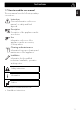
Instructions EN EN 1.7 How to read the user manual This user manual uses the following reading conventions: Instructions General information on this user manual, on safety and final disposal. Description Description of the appliance and its accessories. Use Information on the use of the appliance and its accessories, cooking advice. Cleaning and maintenance Information for proper cleaning and maintenance of the appliance.
Description 2 Description 2.
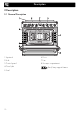
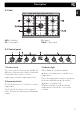
Description AUX = Auxiliary SR = Semi-rapid EN EN 2.2 Hob R = Rapid DUAL = Ultra rapid 2.3 Control panel 1 Function knob 3 Indicator light The oven’s various functions are suitable for different cooking modes. After selecting the required function, set the cooking temperature using the temperature knob. When flashing, it indicates that the appliance is heating up to reach the set temperature.
Description 4 Hob burner knobs Shelves For lighting and adjusting the hob burners. Press and turn the knobs anti-clockwise to in order to light the relative burners. Turn the knobs to the zone between the maximum The appliance features shelves to position trays and racks at different heights. The insertion heights are indicated from the bottom upwards (see 2.1 General Description). and minimum Interior lighting setting to adjust the flame. Return the knobs to the off the burners.
Description Rack To be placed over the top of the oven tray; for cooking foods which may drip. Useful for supporting containers with food during cooking. Deep tray EN EN Tray rack Some models are not provided with all accessories. The accessories intended to come into contact with food are made of materials that comply with the provisions of current legislation. Useful for collecting fat from foods placed on the rack above and for cooking pies, pizzas and baked desserts.
Use 3 Use Instructions High temperature inside the oven during use Danger of burns • Keep the oven door closed during cooking. • Protect your hands wearing heat resistant gloves when moving food inside the oven. • Do not touch the heating elements inside the oven. • Do not pour water directly onto very hot trays. • Keep children under the age of 8 away from the oven when it is in use.
High temperature inside the storage compartment Danger of fire or explosion • Do not spray any spray products near the appliance. • Do not use or leave flammable materials near the appliance or the storage compartment. • Do not use plastic cookware or containers for cooking food. • Do not put sealed tins or containers in the oven. • Never leave the appliance unattended during cooking operations where fats or oils could be released. • Remove all trays and racks which are not required during cooking.
Use 3.1 To save energy 3.2 Using the accessories • Only preheat the appliance if the recipe requires you to do so. • Unless otherwise indicated on the package, defrost frozen foods before placing them in the oven. • When cooking several types of food it is recommended to cook the foods one after the other to make the best use of the already hot oven. • Use dark metal moulds: They help to absorb the heat better. • Remove all trays and racks which are not required during cooking.
Racks and trays Rotisserie Racks and trays have to be inserted into the side guides until they come to a complete stop. The mechanical safety locks that prevent the rack from being removed accidentally must face downwards and towards the back of the oven cavity. 1. Insert the 4 supplied bushings in the 4 corner holes of the deep tray and screw them onto the ring nuts with a suitable tool (such as a screwdriver). Gently insert racks and trays into the oven until they come to a stop. 2.
Use 3. Prepare the rotisserie rod with the food using the clip forks provided. The clip forks can be tightened using the fastening screws. 5. Place the tray on the first runner (see “General Description”). 6. Insert the tip of the rod in the rotisserie motor housing on the left of the rear wall of the oven. 4. Once you have prepared the rotisserie rod, place it on the supports. Insert the tip of the rod as far as it will go into the housing of the mechanism on the lefthand support.
7. To activate the rotisserie, turn the function knob to the position and set the cooking temperature using the temperature knob. Pour a little water into the tray to prevent smoke from forming. 8. When cooking is complete, remove the tray with the rotisserie. 9. Screw on the handle provided so that you can handle the rotisserie rod more easily. 3.3 Using the hob All the appliance’s control and monitoring devices are located together on the front panel.
Use Correct positioning of the flamespreader crowns and burner caps Before lighting the hob burners, make sure that the flame-spreader crowns are correctly positioned in their housings with their respective burner caps. Make sure that the holes 1 of the flame-spreader crowns are aligned with the thermocouples 2 and igniters 3. 3.4 Using the storage compartment There is a storage compartment located at the bottom of the cooker; this can be used to store pans or metal objects required for its use.
Functions list Convection As the heat comes from above and below at the same time, this system is particularly suitable for certain types of food. Traditional cooking, also known as convection cooking, is suitable for cooking just one dish at a time. Perfect for all types of roasts, bread and cakes, and in any case, particularly suitable for fatty meats such as goose and duck.
Use Fan forced The combination of the fan and the circulaire heating element (incorporated in the rear of the oven) allows you to cook different foods on several levels, as long as they need the same temperatures and same type of cooking. Hot air circulation ensures instant and even distribution of heat. It will be possible, for instance, to cook fish, vegetables and biscuits simultaneously (on different levels) without odours and flavours mingling.
3.6 Cooking advice General advice • Use a fan assisted function to achieve consistent cooking at several levels. • It is not possible to shorten cooking times by increasing the temperature (the food could be overcooked on the outside and undercooked on the inside). Advice for cooking meat • Cooking times vary according to the thickness and quality of the food and to consumer taste. • Use a meat thermometer when roasting meat, or simply press on the roast with a spoon.
Use Advice for defrosting and proving • Place frozen foods without their packaging in a lidless container on the first shelf of the oven. • Avoid overlapping the food. • To defrost meat, use the rack placed on the second level and a tray on the first level. In this way, the liquid from the defrosting food drains away from the food. • The most delicate parts can be covered with aluminium foil. • For successful proving, a container of water should be placed in the bottom of the oven.
Setting the time If the time is not set, the oven will not switch on. On the first use, or after a power failure, the digits will be flashing on the appliance’s display. 1. Press the and buttons at the same time. The dot between the hours and the minutes flashes. 2. The time can be set using the or button. Keep the button pressed in to increase or decrease rapidly. 3. Press the button or wait 5 seconds. The dot between the hours and the minutes stops flashing. 4.
Use 6. Press the and buttons at the same time to reset the programmer clock. It is not possible to set a cooking time of more than 10 hours. activate. The current time and the After the setting, to display the cooking time left press the button. and symbols will appear on the display. 5. At the end of cooking the heating elements will be deactivated. On the To reset the set program, press the and buttons at the same time and switch off the oven manually.
Adjusting the buzzer volume Minute minder timer The minute minder timer does not stop the cooking operation but rather informs the user when the set time has run out. The minute minder timer can be activated at any time. 1. Press the button. The display shows the digits and the indicator light flashing between the hours and the minutes. The buzzer volume can be set to 3 different levels. When the buzzer is in operation, press the button to change the setting.
Use Cooking information table Food Lasagne Pasta bake Weight (Kg) Function Shelf Temp. (°C) Time (minutes) 3-4 3-4 Convection Convection 1 1 220 - 230 220 - 230 45 - 50 45 - 50 Fan forced/Fan assisted Fan forced/Fan assisted Fan grill Fan forced/Fan assisted Fan forced Fan forced/Fan assisted Fan forced/Fan assisted Fan forced/Fan assisted 2 2 4 2 2 2 2 2 180 - 190 180 - 190 MAX 200 180 - 190 180 - 190 180 - 190 180 - 190 Veal roast 2 Pork loin 2 Sausages 1.5 Roast beef 1 Roast rabbit 1.
Cleaning and maintenance Instructions Improper use Risk of damage to surfaces • Do not use steam jets to clean the appliance. • Do not use cleaning products containing chlorine, ammonia or bleach on parts made of steel or that have metallic surface finishes (e.g. anodizing, nickelor chromium-plating). • Do not use abrasive or corrosive detergents (e.g. scouring powders, stain removers and metallic sponges) on glass parts. • Do not use rough or abrasive materials or sharp metal scrapers.
Cleaning and maintenance 4.1 Cleaning the hob Igniters and thermocouples Cooking hob pan support grids For correct operation the igniters and thermocouples must always be perfectly clean. Check them frequently and clean them with a damp cloth if necessary. Remove any dry residues with a wooden toothpick or a needle. Remove the pan support grids and clean them in lukewarm water and non-abrasive detergent. Make sure to remove any encrustations. Dry them thoroughly and return them to the hob.
4.2 Cleaning the door Removing the door For easier cleaning it is recommended to remove the door and place it on a tea towel. To remove the door proceed as follows: 1. Open the door completely and insert two pins into the holes on the hinges indicated in the figure. 3. To reassemble the door, put the hinges in the relevant slots in the oven, making sure that grooved sections A are resting completely in the slots. Lower the door and once it is in place remove the pins from the holes in the hinges.
Cleaning and maintenance Removing the internal glass panes For easier cleaning the internal glass panes of the door can be removed. 1. Open the door. 2. Position the retaining clips in the holes in the hinges in order to prevent accidental closing of the door. 3. Pull the rear part of the internal glass pane gently upwards, following the movement indicated by the arrows (1). 5. Remove the intermediate glass pane by lifting it upwards. 6. Clean the external glass pane and the panes removed previously.
4.3 Cleaning the oven cavity Removing racks/trays support frames In order to keep your oven in the best possible condition, clean it regularly after letting it cool down. Avoid letting food residue dry inside the oven cavity, as this could damage the enamel. Take out all removable parts before cleaning. For easier cleaning, we recommend removing: • The door • The rack/tray support frames • The seal. Removing the guide frames enables the sides to be cleaned more easily.
Cleaning and maintenance Cleaning the top section The oven cavity is fitted with a tilting heating element which facilitates cleaning the top part (roof) of the oven. 1. Free the upper heating element by gently lifting it and rotating its retainers by 90 degrees. 4.4 Vapor Clean Vapor Clean is an assisted cleaning procedure which facilitates the removal of dirt. Thanks to this process, it is possible to clean the inside of the oven very easily.
• Pour approximately 40 cc of water into the tray. Make sure it does not overflow out of the cavity. Vapor Clean cycle setting 1. Set a cooking time of 18 minutes using the programmer clock. 2. Turn the function knob to the symbol and the temperature knob to the symbol. The Vapor Clean cycle starts a few seconds after the last press on the programmer clock buttons. 3.
Cleaning and maintenance 4.5 Extraordinary maintenance 4. Slide out and remove the light bulb. Replacing the internal light bulb Live parts Danger of electrocution • Unplug the appliance. The oven is fitted with a 40W light bulb. 1. Completely remove all accessories from inside the oven. 2. Remove the rack/tray support frames. 3. Remove the bulb cover using a tool (e.g. a screwdriver). Do not touch the halogen light bulb directly with your fingers, but wrap it in insulating material. 5.
Installing and removing the seal What to do if... To remove the seal: • Unhook the clips located in the 4 corners and in the centre, then pull the seal outwards. The appliance is not working properly: • The switch is defective: check the fuse box to see whether the switch is in working order. • Loss of power: check that the appliance indicator lights are operational. The gas burner does not light: • Loss of power or moisture in the igniters: light the gas burner with a lighter or match.
Installation 5 Installation 5.1 Minimum clearance to combustible surfaces Freestanding cooker A 600 mm (Overhead) measured from the highest part of the highest burner and 750 mm for an exhaust fan. B 200 mm (Vertical combustible surface) measured form the edge of the nearest burner. C 10 mm (Horizontal combustible surface) below the hob. Refer to AS/NZS 5601 (Protection of a combustible surface) if the above minimum clearances cannot be achieved.
Connection of the appliance to the gas supply must be in accordance with the requirements of AS5601. A ½” BSP connector at the inlet is recommended and the gas supply line to the appliance must be of adequate length to allow sufficient withdrawal of appliance for service or disconnection and be: annealed copper pipe or; flexible hose according to AS/NZ1869 & be at least Class “B”, 10 mm diameter.
Installation or via forced extraction. An efficient extraction system requires precision planning by a specialist qualified in this area and must comply with the positions and clearances indicated by the applicable standards. When the job is complete, the installer must issue a certificate of conformity. 5.3 Adaptation to different types of gas In case of operation with other types of gas, the burner nozzles must be changed and the minimum flame adjusted on the gas cocks. Replacing nozzles 1.
3. Replace the burners in their respective housings. Adjusting the minimum setting for natural or city gas Light the burner and turn it to the minimum position. Extract the gas cock knob and turn the adjustment screw next to the gas cock spindle (depending on the model) until the correct minimum flame is achieved. Refit the knob and verify that the burner flame is stable. Turn the knob rapidly from the maximum to the minimum setting: The flame should not go out. Repeat the operation on all gas cocks.
Installation Burner and nozzle characteristics table 1 ULPG 2.75 kPa AUX SR R Nominal gas consumption (MJ/h) 4.0 6.5 10.8 Injector (1/100 mm) 2 NG 1.0 kPa 0.54 AUX 0.68 SR 0.88 R Nominal gas consumption (MJ/h) 4.5 7.5 12 Injector (1/100 mm) 0.9 1.20 1.55 DUAL int. DUAL ext. 17 0.48 DUAL int. 1.00 DUAL ext. 17 0.81 1.70 The nozzles not provided are available at Authorised Service Centres. 5.
Installation B - Class 2 subclass 1 (Built-in appliance) A 900 mm B 600 mm C1 D min. 150 mm 900 - 915 mm H 750 mm I 450 mm L2 900 mm EN EN Appliance overall dimensions 1 Minimum distance from side walls or other flammable material. 2 Minimum cabinet width (=A). C - Class 2 subclass 1 (Built-in appliance) The appliance must be installed by a qualified technician and according to the regulations in force.
Installation Appliance dimensions Position of gas and electrical connections. Fastening to the wall with brackets The anti-tip devices must be installed in order to prevent the appliance from tipping over. 1. Screw the wall fastening plate to the rear of the appliance. Positioning and levelling Heavy appliance Risk of damage to the appliance • Insert the front legs first and then the rear ones. The appliance must sit level on the floor to ensure stability.
3. Assemble the fastening bracket. 4. Align the base of the hook on the fastening bracket with the base of the slot on the wall fastening plate. 5. Align the base of the fastening bracket with the ground and tighten the screws to fix the measurements. 6. Use 50 mm for the distance from the side of the appliance to the bracket holes.
Installation 7. Move the bracket onto the wall and mark the position of the holes to be drilled in the wall. Assembling the upstand The upstand provided is an integral part of the product. It must be fastened to the appliance prior to installation. The upstand must always be positioned and secured correctly on the appliance. 1. Loosen the 6 screws on the back of the hob (A) and unscrew the 2 screws (B) on the side part of the upstand. 8.
Installation The plinth provided is an integral part of the product; it must be fastened to the appliance prior to installation. The plinth must always be positioned and secured correctly on the appliance. 1. Place the plinth in the front bottom part of the appliance. 5.5 Electrical connection EN EN Mounting the plinth Power voltage Danger of electrocution • Have the electrical connection performed by authorised technical personnel. • Use personal protective equipment.
Installation The appliance can work in the following modes: • 220-240 V 1N~ 3 x 1.5 mm² three-core cable. The values indicated refer to the cross-section of the internal conductor. The aforementioned power cables are sized taking into account the coincidence factor (in compliance with standard EN 60335-2-6). Fixed connection Fit the power line with an all-pole circuit breaker with a contact opening of at least 3 mm in compliance with installation regulations.
914779526/A