Contents 1.1 1.2 1.3 1.4 1.5 1.6 1.7 How to read the user manual This user manual Appliance purpose General safety instructions Manufacturer liability Identification plate Disposal 2 Description 2.1 2.2 2.3 2.4 2.5 General description Cooking hob Control panel Other parts Available accessories 3 Use 3.1 3.2 3.3 3.4 3.5 3.6 3.7 Instructions Cleaning the appliance Removing the door Cleaning the door glazing Cleaning the inside of the oven Extraordinary maintenance 5 Installation 5.1 5.2 5.3 5.4 5.
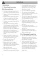
Instructions 1 Instructions 1.1 General safety instructions Risk of personal injury • During use the appliance and its accessible parts become very hot. • Never touch the heating elements during use. • Keep children under eight years of age at a safe distance if they are not constantly supervised. • Children must never play with the appliance.
• Use wooden or plastic utensils. • Do not seat on the appliance. • Do not use steam jets for cleaning the appliance. • Do not obstruct ventilation openings and heat dispersal slots. • Never leave the appliance unattended during cooking operations where fats or oils could be released. • Never leave objects on the cooking surface. • Do not use the appliance to heat rooms for any reason. • Remove any food residues or large spills from previous cooking operations from the inside of the oven.
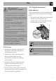
Instructions • Consign the appliance to the appropriate selective collection centres for electrical and electronic equipment waste, or deliver it back to the retailer when purchasing an equivalent product, on a one for one basis. Our appliances are packed in nonpolluting and recyclable materials. • Consign the packing materials to the appropriate selective collection centres. Plastic packaging Danger of suffocation • Do not leave the packaging or any part of it unattended.
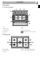
Description EN 2 Description 2.1 General description 1 Skirt 2 Cooking hob 3 Control panel 4 Oven light 5 Seal 6 Door 7 Fan 8 Storage compartment Shelf for racks/trays support frames 2.
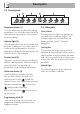
Description 2.3 Control panel Temperature knob (1) 2.4 Other parts This knob allows you to select the cooking temperature. Turn the knob clockwise to the required value, between the minimum and maximum settings. Oven shelves Indicator light (2) The indicator light comes on to indicate that the oven is heating up. It turns off as soon as it reaches the set temperature. It flashes regularly to indicate that the temperature set inside the oven is kept constant.
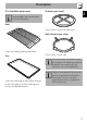
Description Reduction pan stand EN 2.5 Available accessories Some models are not provided with all accessories. Rack Useful when using small cookware. Wok reduction pan stand Useful for holding cooking containers. Tray Useful when using a wok. The accessories intended to come into contact with food are made of materials that comply with the provisions of current legislation. Useful for collecting fat from foods placed on the rack above and for cooking pies, pizzas and baked desserts.
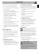
Use 3 Use 3.1 Instructions High temperature inside the oven during use Danger of burns • Keep the oven door closed during cooking. • Protect your hands using heat resistant gloves when moving food inside the oven. • Do not touch the heating elements inside the oven. • Do not pour water directly on very hot trays. • Young children should be supervised to ensure that they do not play with the appliance.
Use • Do not spray aerosols in the vicinity of this appliance while it is in operation. • Do not use or store flammable materials in the appliance storage drawer or near this appliance. • Do not use plastic kitchenware or containers when cooking food. • Do not put sealed tins or containers in the oven. • Do not leave the oven unattended during cooking operations where fats or oils could be released. • Remove from the oven compartment all trays and racks not used during cooking.
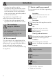
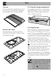
Use Tray rack 3.4 Using the storage compartment The tray has to be inserted into the rack. In this way fat can be collected separately from the food which is being cooked. The storage compartment is at the bottom right of the cooker. It can be used to store cookware or metallic objects necessary when using the appliance. 3.5 Using the hob Reduction pan stands The reduction pan stands have to be placed on the hob grids. Make sure they are properly placed.
Use Before lighting the hob burners, make sure that the flame-spreader crowns are correctly positioned in their housings with their respective burner caps. Make sure that the holes in the flame-spreader crowns are aligned with the igniters and thermocouples (A). 3.6 Using the oven EN Correct position for flame-spreader crowns and burner caps Switching on the oven To switch the oven on: 1. Select the cooking function using the function knob. 2. Select the temperature using the temperature knob.
Use Grill The heat coming from the grill element gives perfect grilling results above all for thin and medium thickness meat and in combination with the rotisserie (where fitted) gives the food an even browning at the end of cooking. Perfect for sausages, spare ribs and bacon. This function enables large quantities of food, particularly meat, to be grilled evenly. Fan with grill The air produced by the fan softens the strong heatwave generated by the grill, grilling perfectly even very thick foods.
3.7 Cooking advice General advice • Use a fan-assisted function to achieve uniform cooking at several levels. • It is not possible to shorten cooking times by increasing the temperature (the food could be overcooked on the outside and undercooked on the inside). • Using more ovens at the same time might affect the final cooking results. Advice for cooking meat • Cooking times vary according to the thickness and quality of the food and to consumer taste.
Use Advice for defrosting and proving • Place frozen foods without their packaging in a lidless container on the first shelf of the oven. • Avoid overlapping the food. • To defrost meat, use the rack placed on the second level and a tray on the first level. In this way, the liquid from the defrosting food drains away from the food. • The most delicate parts can be covered with aluminium foil. • For successful proving, a container of water should be placed in the bottom of the oven.
Use Timed cooking is the function which allows a cooking operation to be started and then ended after a specific length of time set by the user. 1. After selecting a cooking function and temperature, press key . The display will shows the digits and the symbol displayed between the hours and the minutes. 2. Use the key or to set the required minutes. 3. Wait approx. 5 seconds without pressing any key in order for the function to activate. The current time and the symbols and will appear on the display. 4.
Use Adjusting the buzzer volume Timer The timer does not stop the cooking but rather informs the user when the set time has run out. The timer can be activated at any time. 1. Press key. The display will shows the digits and the indicator light flashing between the hours and the minutes. 2. Use the or key to set the required minutes. 3. Wait approx. 5 seconds without pressing any key to finish setting the timer. The current time and the symbols and appear on the display.
Use Food Runner Temperature position from (°C) the bottom 1 220 - 230 1 220 - 230 EN Cooking information table Weight (Kg) Function Lasagne Pasta bake 3-4 3-4 Static Static Roast veal Pork Sausages Roast beef Roast rabbit Turkey breast Roast pork neck Roast chicken 2 2 1.5 1 1.5 3 2-3 1.2 Turbo Turbo Fan with grill Turbo Circulaire Turbo Turbo Turbo 2 2 4 2 2 2 2 2 180 - 190 180 - 190 280 200 180 - 190 180 - 190 180 - 190 180 - 190 Pork chops Spare ribs Bacon Pork fillet Beef fillet 1.5 1.
Cleaning and maintenance 4 Cleaning and maintenance 4.1 Instructions Improper use Risk of damage to surfaces • Do not use a steam cleaner to clean the cooker. • Do not use cleaning products containing chlorine, ammonia or bleach on steel parts or parts with metallic finishes on the surface (e.g. anodizing, nickel- or chromium-plating). • Do not use abrasive or corrosive detergents on glass parts (e.g. powder products, stain removers and metallic sponges).
Igniters and thermocouples For correct operation the igniters and thermocouples must always be perfectly clean. Check them frequently and clean them with a damp cloth if necessary. Remove any dry residues with a wooden toothpick or a needle. 4.3 Removing the door 2. Grasp the door on both sides with both hands, lift it forming an angle of around 30° and remove it. 3.
Cleaning and maintenance 4.5 Cleaning the inside of the oven For the best oven upkeep, clean it regularly after having allowed it to cool. • Take out all removable parts. 1. unscrew the two fastening pins of the frame. 2. pull out the frame toward the interior. If self-cleaning panels are fitted they have to be removed together wit the frame. • Clean the oven racks with warm water and non-abrasive detergent. Carefully rinse and dry the damp parts.
4.6 Extraordinary maintenance Live parts Danger of electrocution • Disconnect the oven power supply. Replacing the internal light bulb 1. Completely remove all accessories from inside the oven. 2. Remove the racks/trays support frames. 3. Remove the bulb cover using a tool (e.g. a screwdriver). 5. Replace the lamp with one of the same type (40W). 6. Refit the cover correctly, so that the moulded part of the glass is facing the door. 7.
Cleaning and maintenance 5 Installation 5.1 Clearances above and around domestic appliances This appliance must be installed by an authorised person in accordance with this instruction manual, AS/NZS 5601.1 – Gas installations (installation and pipe sizing), local gas fitting regulations, local electrical regulations, Building Code of Australia and any other government authority. Requirements 1.
Installation Notes 1. Requirement 3 does not apply to a freestanding or elevated cooking appliance which is designed to prevent flames or the cooking vessels from extending beyond the periphery of the appliance. 2. The ‘cooking surface area’ is defined as that part of the appliance where cooking normally takes place and does not include those parts of the appliance containing control knobs. 3. For definition of hob, see Clause 1.4.64. 4. For definition of trivet, see Clause 1.4.109. 5.
Installation Connection of the appliance to the gas supply must be in accordance with the requirements of AS5601. A ½” BSP connector at the inlet is recommended and the gas supply line to the appliance must be of adequate length to allow sufficient withdrawal of appliance for service or disconnection and be: 1. annealed copper pipe or; 2. flexible hose according to AS/NZ1869 & be at least Class “B”, 10 mm diameter.
Installation EN Connection to liquid gas Use a pressure regulator and make the connection on the gas cylinder following the guidelines set out in the regulations in force. Make sure that the supply pressure complies with the values indicated in the paragraph “ Burner and nozzle characteristics table”. Room ventilation The room containing the appliance should have a permanent air supply in accordance with the standards in force.
Installation 5.3 Adaptation to different types of gas The appliance is pre-set for natural gas at a pressure of 1.0 kPa. Refit the knob and verify that the burner flame is stable. Turn the knob rapidly from the maximum to the minimum setting: the flame should not go out. Repeat the operation on all gas taps. In case of operation with other types of gas, the burner nozzles must be changed and the minimum flame adjusted on the gas taps. Replacing nozzles 1.
Installation 1 ULPG 2.75 kPa AUX SR R UR2 int Nominal gas consumption (MJ/h) Injector (1/100 mm) 3.9 54 6.3 68 10.8 88 50 100 2 NG 1.0 kPA AUX SR R UR2 int UR2 est Nominal gas consumption (MJ/h) Injector (1/100 mm) 3.9 90 7.5 120 12 155 90 5.4 Electrical connection Power voltage Danger of electrocution • Have the electrical connection performed by authorised technical personnel. • Use personal protective equipment.
Installation 5.5 Positioning The values indicated above refer to the cross-section of the internal conductor. The aforementioned power cables are sized taking into account the coincidence factor (in compliance with standard EN 60335-2-6). Fixed connection Fit the power line with an omnipolar circuit breaker in compliance with installation regulations. The circuit breaker should be located near the appliance and in an easily reachable position.
Installation EN Depending on the type of installation, this appliance belongs to classes: C - Class 2 subclass 1 A - Class 1 (Free-standing appliance) (Built-in appliance) The appliance must be installed by a qualified technician and according to the regulations in force. If the appliance is installed on a raised platform, secure it using suitable fastening systems. DO NOT MODIFY THIS APPLIANCE.
Installation Assembling the skirt Mounting the toe skirt The backguard provided is an integral part of the product; it must be fastened to the appliance prior to installation. The toe skirt provided is an integral part of the product; it must be fastened to the appliance prior to installation. The backguard must always be positioned and secured correctly on the appliance. 1. Loosen the 6 screws on the back of the top (A) and unscrew the 2 screws (B) on the side part of the backguard.
Wall fixing Positioning and levelling the appliance 1. Attach the chain to the cooker 2. Stretch out the chain attached to the cooker horizontally so that the other end touches the wall. 3. Mark the wall in the position where the hole is to be drilled. 4. Drill the hole, insert a wall plug and attach the chain. 5. Once the chain is in position, push the cooker against the wall and reduce the amount of chain links to keep the chain tight to prevent any excess movement.