Contents 1.1 1.2 1.3 1.4 1.5 1.6 1.7 General safety instructions Appliance purpose Manufacturer liability This user manual Identification plate Disposal How to read the user manual 2 Description 2.1 2.2 2.3 2.4 2.5 General Description Cooking hob Control panel Other parts Available accessories 3 Use 3.1 3.2 3.3 3.4 3.5 3.6 3.7 3.8 Instructions Cleaning the appliance Vapour Clean Removing the door Cleaning the door glazing Extraordinary maintenance 5 Installation 5.1 5.2 5.3 5.4 5.5 5.
Instructions 1 Instructions 1.1 General safety instructions Risk of personal injury • During use the appliance and its accessible parts become very hot. Never touch the heating elements during use. • Protect your hands by wearing oven gloves when handling food inside the oven cavity. • Never try to put out a fire or flames with water: turn off the appliance and smother the flames with a fire blanket or other appropriate cover.
• If you need to move food or at the end of cooking, open the door 5 cm for a few seconds, let the steam come out, then open it fully. • Do not open the storage compartment (if present) when the oven is on and still hot. • The items inside the storage compartment could be very hot after the oven has been used. • DO NOT USE OR STORE FLAMMABLE MATERIALS IN THE APPLIANCE STORAGE DRAWER OR NEAR THIS APPLIANCE. • DO NOT SPRAY AEROSOLS IN THE VICINITY OF THIS APPLIANCE WHILE IT IS IN OPERATION.
Instructions • Never leave the appliance unattended during cooking operations in which fats or oils could be released that could overheat and catch fire. Be very careful. • Danger of fire: do not store items on the cooking surfaces. • DO NOT USE THIS APPLIANCE AS A SPACE HEATER. • DO NOT PLACE ARTICLES ON OR AGAINST THIS APPLIANCE. • Do not spray any spray products near the oven. • Do not use plastic kitchenware or containers when cooking food. • Do not put sealed tins or containers in the oven.
• Never use the oven door to lever the appliance into place when fitting. • Avoid exerting too much pressure on the oven door when open. • Do not use the handle to lift or move the appliance. Installation • THIS APPLIANCE MUST NOT BE INSTALLED IN BOATS OR CARAVANS. • The appliance must not be installed on a stand. • Position the appliance into the cabinet cutout with the help of a second person. • To prevent overheating, the appliance must not be installed behind a decorative door or a panel.
Instructions 1.3 Manufacturer liability The manufacturer declines all liability for damage to persons or property caused by: • use of the appliance other than the one envisaged; • non-observance of the user manual provisions; • tampering with any part of the appliance; • use of non-original spare parts. 1.6 Disposal To dispose of the appliance: • Cut the power supply cable and remove it along with the plug. 1.
Instructions EN 1.7 How to read the user manual This user manual uses the following reading conventions: Instructions General information on this user manual, on safety and final disposal. Description Description of the appliance and its accessories. Use Information on the use of the appliance and its accessories, cooking advice. Cleaning and maintenance Information for proper cleaning and maintenance of the appliance. Installation Information for authorised persons: installation, operation and inspection.
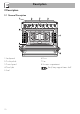
Description 2 Description 2.
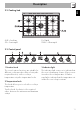
Description AUX = Auxiliary SR = Semi-rapid EN 2.2 Cooking hob R = Rapid DUAL = Ultra rapid 2.3 Control panel 1 Function knob 3 Indicator light The oven's various functions are suitable for different cooking modes. After selecting the required function, set the cooking temperature using the temperature knob. The indicator light comes on to indicate that the oven is heating up. It turns off as soon as it reaches the set temperature.
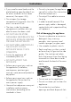
Description 4 Hob burner knobs Cooling fan Useful for lighting and adjusting the hob burners. Press and turn the knobs anti-clockwise to the value to light the relative burners. Turn the knobs to the zone between the maximum and minimum setting to adjust the flame. Return the knobs to the position to turn off the burners. The fan cools the ovens and comes into operation during cooking.
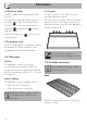
Description Reduction pan stand EN Tray rack Useful when using small cookware. WOK reduction pan stand To be placed over the top of the oven tray; for cooking foods which may drip. Deep tray Useful when using a wok. The accessories intended to come into contact with food are made of materials that comply with the provisions of current legislation. Useful for collecting fat from foods placed on the rack above.
Use 3 Use 3.1 Instructions High temperature inside the oven during use Danger of burns • Keep the oven door closed during cooking. • Protect your hands wearing heat resistant gloves when moving food inside the oven. • Do not touch the heating elements inside the oven. • Do not pour water directly onto very hot trays. • Do not allow children younger than 8 years old to come near the appliance when in operation.
High temperature inside the oven during use Danger of fire or explosion • Do not spray any spray products near the oven. • Do not use or leave flammable materials near the oven or the storage compartment. • Do not use plastic kitchenware or containers when cooking food. • Do not put sealed tins or containers in the oven. • Do not leave the oven unattended during cooking operations where fats or oils could be released. • Remove all trays and racks which are not required during cooking.
Use 3.3 Using the accessories Racks and trays Reduction pan stands Racks and trays have to be inserted into the side guides until they come to a complete stop. • The mechanical safety locks that prevent the rack from being taken out accidentally have to face downwards and towards the oven back. The reduction pan stands have to be placed on the hob grids. Make sure they are properly placed. Gently insert racks and trays into the oven until they come to a stop.
Rotisserie rod 1. Insert the 4 supplied bushings in the 4 corner holes of the deep tray and screw them onto the ring nuts with a suitable tool (such as a screwdriver). 2. Position the rotisserie supports in the bushings as shown in the figure below. 3. Prepare the rotisserie rod with the food using the clip forks provided. The clip forks can be tightened using the fastening screws. 4. Once you have prepared the rotisserie rod, place it on the supports.
Use 6. Insert the tip of the rod in the rotisserie motor housing on the left of the rear wall of the oven. 8. When cooking is complete, remove the tray with the rotisserie. 9. Screw on the handle provided so that you can handle the rotisserie rod more easily. 3.4 Using the storage compartment These operations must be performed with the oven off and cold. 7. To activate the rotisserie, turn the function knob to the position and set the cooking temperature using the temperature knob.
Use All the appliance's control and monitoring devices are located together on the front panel. The burner controlled by each knob is shown next to the knob. The appliance is equipped with an electronic ignition device. Simply press the knob and turn it anticlockwise to the maximum flame symbol, until the burner lights. If the burner does not light in the first 15 seconds, turn the knob to and wait 60 seconds before trying again.
Use 3.6 Using the oven Switching on the oven To switch on the oven: 1. Select the cooking function using the function knob. 2. Select the temperature using the temperature knob. Ensure that the programmer clock shows the cooking duration symbol , otherwise it will not be possible to turn on the oven. Press the key to reset the programmer clock. Functions list Convection As the heat comes from above and below at the same time, this system is particularly suitable for certain types of food.
Fan assisted The operation of the fan, combined with traditional cooking, ensures consistent cooking even with complex recipes. Perfect for biscuits and cakes, even when simultaneously cooked on several levels. (For multiple-level cooking, we recommend using the 2nd and 4th shelf).
Use 3.7 Cooking advice General advice • Use a fan assisted function to achieve consistent cooking at several levels. • It is not possible to shorten cooking times by increasing the temperature (the food could be overcooked on the outside and undercooked on the inside). Advice for cooking meat • Cooking times vary according to the thickness and quality of the food and to consumer taste. • Use a meat thermometer when roasting meat, or simply press on the roast with a spoon.
Use 3.8 Programmer clock Setting the time EN To save energy • Stop cooking a few minutes before the time normally used. Cooking will continue for the remaining minutes with the heat which has accumulated inside the oven. • Reduce any opening of the door to a minimum to avoid heat dispersal. • Keep the inside of the appliance clean at all times. If the time is not set, the oven will not switch on. On the first use, or after a power failure, the digits will be flashing on the appliance’s display. 1.
Use Timed cooking Timed cooking is the function which allows a cooking operation to be started and then ended after a specific length of time set by the user. 1. After selecting a cooking function and temperature, press the key . The After the setting, to display the cooking time left press the key . To reset the set program, press the keys and at the same time and switch off the oven manually. display will show the digits and the symbol displayed between the hours and the minutes. 2.
5. At the end of cooking the heating elements will be deactivated. On the display, the symbol turns off, the symbol flashes and the buzzer sounds. 6. To turn off the buzzer just press any key of the programmer clock. 7. Press the keys and at the same time to reset the programmer clock. After the setting, to display the cooking time left press the key . To display the end of cooking time, press the key 3. Wait approx. 5 seconds without pressing any key to finish setting the minute minder.
Use Cooking information table Weight (Kg) Function Shelf Temperature (°C) Time (minutes) Lasagne Pasta bake 3-4 3-4 Convection Convection 1 1 220 - 230 220 - 230 45 - 50 45 - 50 Roast veal Pork Sausages Roast beef Roast rabbit Turkey breast Roast pork neck Roast chicken 2 2 1.5 1 1.5 3 2-3 1.
4 Cleaning and maintenance 4.1 Instructions Improper use Risk of damage to surfaces • Do not use steam jets to clean the appliance. • Do not use cleaning products containing chlorine, ammonia or bleach on parts made of steel or that have metallic surface finishes (e.g. anodizing, nickelor chromium-plating). • Do not use abrasive or corrosive detergents (e.g. scouring powders, stain removers and metallic sponges) on glass parts. • Do not use rough or abrasive materials or sharp metal scrapers.
Cleaning and maintenance Cleaning the igniters and thermocouples • If necessary, clean the igniters and thermocouples with a damp cloth. • If there is any dry residue, remove it with a toothpick or needle. For easier cleaning, we recommend removing: • The door • The rack/tray support frames • Removable guides, where fitted • The seal In the event you are using specific cleaning products, we recommend running the oven at maximum temperature for 15-20 minutes in order to eliminate any residue.
Cleaning the top section The oven cavity is fitted with a tilting heating element which facilitates cleaning the top part (roof) of the oven. 1. Free the upper heating element by gently lifting it and rotating its retainers by 90 degrees. 4.3 Vapour Clean Vapour Clean is an assisted cleaning procedure which facilitates the removal of dirt. Thanks to this process, it is possible to clean the inside of the oven very easily.
Cleaning and maintenance • Pour approximately 40 cc of water into the tray. Make sure it does not overflow out of the cavity. Vapour Clean setting 1. Turn the function knob to the symbol the temperature knob to the symbol and . 2. Set a cooking time of 18 minutes using the programmer clock. The Vapour Clean cycle starts a few seconds after the last press on the programmer clock keys. 3.
4.4 Removing the door For easier cleaning it is recommended to remove the door and place it on a tea towel. To remove the door proceed as follows: 1. Open the door completely and insert two pins into the holes on the hinges indicated in the figure. 2. Grasp the door on both sides with both hands, lift it forming an angle of around 30° and remove it. 3. To reassemble the door, put the hinges in the relevant slots in the oven, making sure that grooved sections A are resting completely in the slots.
Cleaning and maintenance Removing the internal glass panes For easier cleaning the internal glass panes of the door can be removed. 1. Open the door. 2. Place the pins into the holes to prevent accidental closing of the door. 3. Pull the rear part of the internal glass pane gently upwards, following the movement indicated by the arrows (1). 5. Remove the intermediate glass pane by lifting it upwards. 6. Clean the external glass pane and the panes removed previously. Use absorbent kitchen roll.
Cleaning and maintenance 4. Slide out and remove the light bulb. EN 4.6 Extraordinary maintenance Replacing the oven light bulb Live parts Danger of electrocution • Unplug the appliance. The oven is fitted with a 40W light bulb. 1. Completely remove all accessories from inside the oven. 2. Remove the racks/trays support frames. 3. Remove the bulb cover using a tool (e.g. a screwdriver). Do not touch the halogen light bulb directly with your fingers, but wrap it in insulating material. 5.
Cleaning and maintenance Removing and installing the oven seal What to do if... To remove the oven seal: • Unhook the clips in the 4 corners and in the centre, then pull the oven seal. The appliance does not work. • The circuit breaker is faulty: look in the fuse box and check that the circuit breaker is in working order. • Power cut: check whether the kitchen light works. The gas burner does not ignite. • Power cut or damp ignition plugs: light the gas burner with a gas lighter or a match.
Installation EN 5 Installation 5.1 Clearances above and around domestic appliances This appliance must be installed by an authorised person in accordance with this instruction manual, AS/NZS 5601.1 – Gas installations (installation and pipe sizing), local gas fitting regulations, local electrical regulations, Building Code of Australia and any other government authority. Requirements 1.
Installation 3. Additional requirements for Freestanding and Elevated Cooking Appliaces – (Measurements D & E) Where D, the distance from the periphery of the nearest burner to a horizontal combustible surface is less than 200 mm, then E shall be 10 mm or more, or the horizontal surface shall be above the trivet. See insets above. Notes 1.
Connection of the appliance to the gas supply must be in accordance with the requirements of AS5601. A ½” BSP connector at the inlet is recommended and the gas supply line to the appliance must be of adequate length to allow sufficient withdrawal of appliance for service or disconnection and be: 1. annealed copper pipe or; 2. flexible hose according to AS/NZ1869 & be at least Class “B”, 10 mm diameter.
Installation 4. If the pressure is 2.75kPa, reassemble the burner and perform the final checks as per this instruction manual. 5. If the pressure is not 2.75kPa, disconnect the appliance and check/adjust/ replace the LPG cylinder regulator(s) as appropriate in accordance with AS/ NZS5601. Connection to liquid gas Combustion gas discharge Combustion gases may be discharged by means of hoods connected to a flue with reliable natural draught, or a fan extraction system.
5.3 Adaptation to different types of gas The appliance is pre-set for natural gas at a pressure of 1.0 kPa. Refit the knob and verify that the burner flame is stable. Turn the knob rapidly from the maximum to the minimum setting: the flame should not go out. Repeat the operation on all gas taps. In case of operation with other types of gas, the burner nozzles must be changed and the minimum flame adjusted on the gas taps. Replacing nozzles 1.
Installation Burner and nozzle characteristics table NG 1.0 kPA AUX SR R DUAL (int + ext) Nominal gas consumption (MJ/h) Injector (1/100 mm) 4.5 90 7.5 120 12 155 18.0 81 + 170 ULPG 2.75 kPa AUX SR R DUAL (int + ext) 4 54 6.5 68 10.8 88 17.2 48 + 100 Nominal gas consumption (MJ/h) Injector (1/100 mm) Appliance dimensions (mm) Location of gas and electrical connection points. 5.
Overall dimensions General information A 900 mm B 600 mm 1 C D 500 mm H 750 mm I 450 mm 2 900 mm L This appliance may be installed next to walls, one of which must be higher than the worktop, at a minimum distance of 50 mm from the side of the appliance, as shown in figures A and C relative to the installation classes. Any wall units positioned above the worktop must be at a minimum distance of at least 600 mm.
Installation Positioning and levelling Heavy appliance Risk of damage to the appliance • Insert the front feet first and then the rear ones. B - Class 2 subclass 1 (Built-in appliance) C - Class 2 subclass 1 (Built-in appliance) The appliance must be installed by authorised persons and according to the regulations in force. If the appliance is installed on a raised platform, secure it using suitable fastening systems. DO NOT MODIFY THIS APPLIANCE.
Assembling the skirt Mounting the toe skirt The backguard provided is an integral part of the product; it must be fastened to the appliance prior to installation. The toe skirt provided is an integral part of the product; it must be fastened to the appliance prior to installation. The backguard must always be positioned and secured correctly on the appliance. 1. Loosen the 6 screws on the back of the top (A) and unscrew the 2 screws (B) on the side part of the backguard.
Installation Wall fixing 1. Turn the screw placed behind the cooktop near the gas connection. 4. Mark the wall in the position where the hole is to be drilled. 5. Drill the hole and insert a wall plug. 2. Attach the chain to the cooker with the screw just removed. 3. Stretch it out horizontally so that the other end of the chain touches the wall. 44 6. Attach the chain and push the appliance to the wall.
Installation Power voltage Danger of electrocution • Have the electrical connection performed by authorised technical personnel. • Use personal protective equipment. • The appliance must be connected to earth in compliance with electrical system safety standards. • Disconnect the mains supply. • Do not pull the cable to remove the plug. • Use cables withstanding a temperature of at least 90°C. • The tightening torque of the screws of the terminal board conductors must be 1.5 - 2 Nm.
Installation 5.6 For the installer • The plug must remain accessible after the installation is complete. Do not kink or trap the mains connection cable. • The appliance must be fitted according to the installation diagrams. • Do not attempt to turn or stress the threaded elbow on the manifold. You risk damage to this part of the appliance which may void the manufacturer’s warranty. • Before leaving check all connections for gas leaks with soap and water. DO NOT use a naked flame for detecting leaks.