Dear Customer, Thank you for having chosen Divina Cucina, domestic appliances from the ‘Sicily is my love’ collection by Smeg – Dolce&Gabbana. By choosing this product, you have selected an appliance that combines the quality and technology of Smeg products and the creativity and design of Dolce&Gabbana.
Contents General safety instructions Manufacturer’s liability Appliance purpose Identification plate This user manual Disposal How to read the user manual 2 Description 2.1 2.2 2.3 2.4 2.5 General Description Hob Control panel Other parts Available accessories 3 Use 3.1 3.2 3.3 3.4 3.5 3.6 3.7 Cleaning the hob Cleaning the door Cleaning the oven cavity Vapor Clean Extraordinary maintenance 5 Installation 5.1 5.2 5.3 5.4 5.
Instructions 1 Instructions 1.1 General safety instructions Risk of personal injury • During use the appliance and its accessible parts become very hot. Never touch the heating elements during use. • Protect your hands by wearing oven gloves when moving food inside the oven. • Never try to put out a fire or flames with water: Turn off the appliance and smother the flames with a fire blanket or other appropriate cover.
• DO NOT USE AEROSOLS IN THE VICINITY OF THIS APPLIANCE WHILST IT IS IN USE. • Switch off the appliance immediately after use. • DO NOT MODIFY THIS APPLIANCE. • Always use any necessary/ required personal protective equipment (PPE) before performing any work on the appliance (installation, maintenance, positioning or movement). • Before performing any work on the appliance, switch off the power supply.
Instructions Risk of damaging the appliance • Do not use abrasive or corrosive detergents (e.g. scouring powders, stain removers and metallic sponges) on glass parts. • Use wooden or plastic utensils. • Racks and trays should be inserted as far as they will go into the side guides. The mechanical safety locks that prevent them from being removed must face downwards and towards the back of the oven cavity. • Do not sit on the appliance. • Do not use steam jets to clean the appliance.
• Do not wash removable parts such as the hob pan support grids, flame-spreader crowns and burner caps in the dishwasher. • Never use the oven door to lever the appliance into place when fitting. • Avoid exerting too much pressure on the oven door when open. • Do not use the handle to lift or move the appliance. Installation • THIS APPLIANCE MUST NOT BE INSTALLED IN BOATS OR CARAVANS. • The appliance must not be installed on a pedestal.
Instructions • Installation using a hose must be carried out so that the length of the hose does not exceed 2 metres when fully extended for steel hoses and 1.5 metres for rubber hoses. • The hoses should not come into contact with moving parts and should not be crushed in any way. • If required, use a pressure regulator that complies with current regulations. • After carrying out any operation, check that the tightening torque of gas connections is between 10 Nm and 15 Nm.
1.4 Identification plate The identification plate bears the technical data, serial number and brand name of the appliance. Do not remove the identification plate for any reason. 1.5 This user manual This user manual is an integral part of the appliance and must therefore be kept in its entirety and within the user’s reach for the whole working life of the appliance. Read this user manual carefully before using the appliance. 1.
Instructions • Deliver the appliance to the appropriate recycling centre for electrical and electronic equipment waste, or return it to the retailer when purchasing an equivalent product, on a one for one basis. Our appliances are packaged in non-polluting and recyclable materials. • Deliver the packing materials to the appropriate recycling centre. Plastic packaging Danger of suffocation • Do not leave the packaging or any part of it unattended. • Do not let children play with the plastic bags. 1.
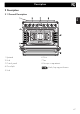
Description EN 2 Description EN 2.
Description 2.2 Hob AUX = Auxiliary SR = Semi-rapid R = Rapid DUAL = Ultra rapid 2.3 Control panel 1 Function knob 3 Indicator light The oven’s various functions are suitable for different cooking modes. After selecting the required function, set the cooking temperature using the temperature knob. The indicator light comes on to indicate that the oven is heating up. It turns off as soon as it reaches the set temperature.
Shelves For lighting and adjusting the hob burners. Press and turn the knobs anti-clockwise to in order to light the relative burners. Turn the knobs to the zone between the maximum The appliance features shelves to position trays and racks at different heights. The insertion heights are indicated from the bottom upwards (see 2.1 General Description). and minimum Interior lighting setting to adjust the flame. Return the knobs to the off the burners.
Description Tray rack Rack To be placed over the top of the oven tray; for cooking foods which may drip. Useful for supporting containers with food during cooking. Deep tray Self-cleaning panels Useful for collecting fat from foods placed on the rack above and for cooking pies, pizzas and baked desserts. Useful for absorbing small grease residues. Rotisserie Some models are not provided with all accessories.
Use Instructions High temperature inside the oven during use Danger of burns • Keep the oven door closed during cooking. • Protect your hands wearing heat resistant gloves when moving food inside the oven. • Do not touch the heating elements inside the oven. • Do not pour water directly onto very hot trays. • Keep children under the age of 8 away from the oven when it is in use.
Use High temperature inside the storage compartment Danger of fire or explosion • Do not spray any spray products near the appliance. • Do not use or leave flammable materials near the appliance or the storage compartment. • Do not use plastic cookware or containers for cooking food. • Do not put sealed tins or containers in the oven. • Never leave the appliance unattended during cooking operations where fats or oils could be released. • Remove all trays and racks which are not required during cooking.
3.2 Using the accessories • Only preheat the appliance if the recipe requires you to do so. • Unless otherwise indicated on the package, defrost frozen foods before placing them in the oven. • When cooking several types of food it is recommended to cook the foods one after the other to make the best use of the already hot oven. • Use dark metal moulds: They help to absorb the heat better. • Remove all trays and racks which are not required during cooking.
Use Racks and trays Rotisserie (on some models only) Racks and trays have to be inserted into the side guides until they come to a complete stop. The mechanical safety locks that prevent the rack from being removed accidentally must face downwards and towards the back of the oven cavity. 1. Insert the 4 supplied bushings in the 4 corner holes of the deep tray and screw them onto the ring nuts with a suitable tool (such as a screwdriver).
5. Place the tray on the first runner (see “General Description”). 6. Insert the tip of the rod in the rotisserie motor housing on the left of the rear wall of the oven. 4. Once you have prepared the rotisserie rod, place it on the supports. Insert the tip of the rod as far as it will go into the housing of the mechanism on the lefthand support. These operations must be performed with the oven off and cold. 75 EN 3. Prepare the rotisserie rod with the food using the clip forks provided.
Use 7. To activate the rotisserie, turn the function knob to the position and set the cooking temperature using the temperature knob. Pour a little water into the tray to prevent smoke from forming. 8. When cooking is complete, remove the tray with the rotisserie. 9. Screw on the handle provided so that you can handle the rotisserie rod more easily. 3.3 Using the hob All the appliance’s control and monitoring devices are located together on the front panel.
Before lighting the hob burners, make sure that the flame-spreader crowns are correctly positioned in their housings with their respective burner caps. Make sure that the holes 1 of the flame-spreader crowns are aligned with the thermocouples 2 and igniters 3. 3.4 Using the storage compartment There is a storage compartment located at the bottom of the cooker; this can be used to store pans or metal objects required for its use. • To open the storage compartment, pull the handle towards you. 3.
Use Functions list Static As the heat comes from above and below at the same time, this system is particularly suitable for certain types of food. Traditional cooking, also known as static cooking, is suitable for cooking just one dish at a time. Perfect for all types of roasts, bread and cakes, and in any case, particularly suitable for fatty meats such as goose and duck.
Fan with circulaire The combination of the fan and the circulaire heating element (incorporated in the rear of the oven) allows you to cook different foods on several levels, as long as they need the same temperatures and same type of cooking. Hot air circulation ensures instant and even distribution of heat. It will be possible, for instance, to cook fish, vegetables and biscuits simultaneously (on different levels) without odours and flavours mingling.
Use 3.6 Cooking advice General advice • Use a fan assisted function to achieve consistent cooking at several levels. • It is not possible to shorten cooking times by increasing the temperature (the food could be overcooked on the outside and undercooked on the inside). Advice for cooking meat • Cooking times vary according to the thickness and quality of the food and to consumer taste. • Use a meat thermometer when roasting meat, or simply press on the roast with a spoon.
Use To save energy • Stop cooking a few minutes before the time normally used. Cooking will continue for the remaining minutes with the heat which has accumulated inside the oven. • Reduce any opening of the door to a minimum to avoid heat dispersal. • Keep the inside of the appliance clean at all times. EN • Place frozen foods without their packaging in a lidless container on the first shelf of the oven. • Avoid overlapping the food.
Use Setting the time If the time is not set, the oven will not switch on. On the first use, or after a power failure, the digits will be flashing on the appliance’s display. 1. Press the and buttons at the same time. The dot between the hours and the minutes flashes. 2. The time can be set using the or button. Keep the button pressed in to increase or decrease rapidly. 3. Press the button or wait 5 seconds. The dot between the hours and the minutes stops flashing. 4.
It is not possible to set a cooking time of more than 10 hours. 3. Use the or button to set the required minutes. 4. Wait approx. 5 seconds without pressing any button in order for the function to activate. The current time and the After the setting, to display the cooking time left press the button. and symbols will appear on the display. 5. At the end of cooking the heating elements will be deactivated.
Use Adjusting the buzzer volume Minute minder timer The minute minder timer does not stop the cooking operation but rather informs the user when the set time has run out. The minute minder timer can be activated at any time. 1. Press the button. The display shows the digits and the indicator light flashing between the hours and the minutes. 2. Use the or button to set the required minutes. 3. Wait approx. 5 seconds without pressing any button to finish setting the minute minder.
Use Lasagne Pasta bake Weight (Kg) Function Shelf Temp. (°C) Time (minutes) 3-4 3-4 Static Static 1 1 220 - 230 220 - 230 45 - 50 45 - 50 Circulaire/Fan assisted Circulaire/Fan assisted Fan with grill Circulaire/Fan assisted Circulaire Circulaire/Fan assisted Circulaire/Fan assisted Circulaire/Fan assisted 2 2 4 2 2 2 2 2 180 - 190 180 - 190 MAX 200 180 - 190 180 - 190 180 - 190 180 - 190 Veal roast 2 Pork loin 2 Sausages 1.5 Roast beef 1 Roast rabbit 1.
Cleaning and maintenance 4 Cleaning and maintenance Instructions Improper use Risk of damage to surfaces • Do not use steam jets to clean the appliance. • Do not use cleaning products containing chlorine, ammonia or bleach on parts made of steel or that have metallic surface finishes (e.g. anodizing, nickelor chromium-plating). • Do not use abrasive or corrosive detergents (e.g. scouring powders, stain removers and metallic sponges) on glass parts.
Igniters and thermocouples Cooking hob pan support grids For correct operation the igniters and thermocouples must always be perfectly clean. Check them frequently and clean them with a damp cloth if necessary. Remove any dry residues with a wooden toothpick or a needle. Remove the pan support grids and clean them in lukewarm water and non-abrasive detergent. Make sure to remove any encrustations. Dry them thoroughly and return them to the hob. EN 4.
Cleaning and maintenance 4.2 Cleaning the door Removing the door For easier cleaning it is recommended to remove the door and place it on a tea towel. To remove the door proceed as follows: 1. Open the door completely and insert two pins into the holes on the hinges indicated in the figure. 3. To reassemble the door, put the hinges in the relevant slots in the oven, making sure that grooved sections A are resting completely in the slots.
For easier cleaning the internal glass panes of the door can be removed. 1. Open the door. 2. Position the retaining clips in the holes in the hinges in order to prevent accidental closing of the door. 3. Pull the rear part of the internal glass pane gently upwards, following the movement indicated by the arrows (1). 5. Remove the intermediate glass pane by lifting it upwards. EN Removing the internal glass panes EN Cleaning and maintenance 6.
Cleaning and maintenance 4.3 Cleaning the oven cavity In order to keep your oven in the best possible condition, clean it regularly after letting it cool down. Avoid letting food residue dry inside the oven cavity, as this could damage the enamel. Take out all removable parts before cleaning. For easier cleaning, we recommend removing: • The door • The rack/tray support frames • The seal.
Cleaning and maintenance Cleaning the top section (on some models only) Removing the side self-cleaning panels and the rack/tray support frames enables the sides to be cleaned more easily. To remove the self-cleaning panels and rack/tray support frames: • Pull the frame towards the inside of the oven to release it from its groove A. Then slide it out of the seats at the back B. The side self-cleaning panel is attached to the rack/tray support frame.
Cleaning and maintenance 4.4 Vapor Clean Vapor Clean is an assisted cleaning procedure which facilitates the removal of dirt. Thanks to this process, it is possible to clean the inside of the oven very easily. The dirt residues are softened by the heat and water vapour for easier removal afterwards. • Pour approximately 40 cc of water into the tray. Make sure it does not overflow out of the cavity.
End of the Vapor Clean cycle 1. Set a cooking time of 18 minutes using the programmer clock. 4. Open the door and wipe away the less stubborn dirt with a microfibre cloth. 5. Use a non-scratch sponge with brass filaments on hard to remove deposits. 6. In case of grease residues use specific oven cleaning products. 7. Remove the water left inside the oven.
Cleaning and maintenance 4.5 Extraordinary maintenance 4. Slide out and remove the light bulb. Replacing the internal light bulb Live parts Danger of electrocution • Unplug the appliance. The oven is fitted with a 40W light bulb. 1. Completely remove all accessories from inside the oven. 2. Remove the rack/tray support frames. 3. Remove the bulb cover using a tool (e.g. a screwdriver). Do not touch the halogen light bulb directly with your fingers, but wrap it in insulating material. 5.
What to do if... To remove the seal: • Unhook the clips located in the 4 corners and in the centre, then pull the seal outwards. The appliance is not working properly: • The switch is defective: check the fuse box to see whether the switch is in working order. • Loss of power: check that the appliance indicator lights are operational. The gas burner does not light: • Loss of power or moisture in the igniters: light the gas burner with a lighter or match.
Installation 5 Installation 5.1 Gas connection Gas leak Danger of explosion • After carrying out any operation, check that the tightening torque of gas connections is between 10 Nm and 15 Nm. • If required, use a pressure regulator that complies with current regulations. • At the end of the installation, check for any leaks with a soapy solution, never with a flame.
Connection with a steel hose Make the connection to the gas mains using a continuous wall steel hose whose specifications comply with the applicable standard. Carefully screw the connector 3 to the gas connector 1 of the appliance, placing the seal 2 between them. Connection with a steel hose with bayonet fitting Connection using a rubber hose complying with current standards is only permitted if the hose can be inspected along its entire length.
Installation Connection with a steel hose with conical fitting Make the connection to the gas mains using a continuous wall steel hose whose specifications comply with the applicable standard. Carefully screw the hose connector 3 to the appliance’s gas connector 1 (½” thread ISO 228-1), placing the supplied seal 2 between them. Apply insulating material to the thread of connector 3, then tighten the steel hose 4 to the connector 3.
5.2 Adaptation to different types of gas EN In case of operation with other types of gas, the burner nozzles must be changed and the minimum flame adjusted on the gas cocks. EN Installation Replacing nozzles 1 Extraction using a hood 2 Extraction without a hood 1. Remove the pan supports, burner caps and flame-spreader crowns to access the burner cups. 2. Replace the nozzles using a 7 mm spanner according to the gas to be used (see Gas types and Countries).
Installation Adjusting the minimum setting for natural or town gas Light the burner and turn it to the minimum position. Extract the gas cock knob and turn the adjustment screw next to the gas cock spindle (depending on the model) until the correct minimum flame is achieved. Refit the knob and verify that the burner flame is stable. Turn the knob rapidly from the maximum to the minimum setting: The flame should not go out. Repeat the operation on all gas cocks.
Gas types and Countries IT GB-IE FR-BE DE AT NL ES PT SE RU DK PL HU Gas types EN Installation 1 Natural Gas G20 20 mbar • • • • • • • • • • EN G20 • G20/25 20/25 mbar 2 Natural Gas G20 G20 • 25 mbar 3 Natural Gas G25 G25 25 mbar G25.3 25 mbar • • 4 Natural Gas G25.1 G25.1 • 25 mbar 5 Natural Gas G25 G25 • 20 mbar 6 Natural Gas G2.350 G2.
Installation Burner and nozzle characteristics table 1 Natural Gas G20 AUX SR R DUAL int. DUAL ext. Rated heating capacity (kW) 1.0 1.8 2.9 0.9 4.10 Nozzle diameter (1/100 mm) 72 97 115 70 150 Pre-chamber (printed on nozzle) (X) (Z) (Y) (H1) (H3) 2 Natural Gas G20 400 AUX 500 SR 800 R 400 DUAL int. 1200 DUAL ext. Rated heating capacity (kW) 1.1 1.8 2.9 0.9 4.
AUX SR R DUAL int. DUAL ext. Rated heating capacity (kW) 1.0 1.8 3.0 0.9 3.8 Nozzle diameter (1/100 mm) 50 65 85 44 96 - - - - - Reduced flow rate (W) 400 500 800 400 1300 Rated flow rate G30 (g/h) 73 131 218 65 276 Rated flow rate G31 (g/h) 8 LPG G30/31 71 AUX 129 SR 214 R 64 DUAL int. 271 DUAL ext. Rated heating capacity (kW) 1.1 1.9 3.0 0.8 3.
Installation 5.3 Positioning Heavy appliance Crushing hazard • Position the appliance into the cabinet cut-out with the help of a second person. Pressure on the open door Risk of damage to the appliance Any wall units installed above the appliance’s worktop must be positioned at least Y mm from it. If a hood is installed above the hob, refer to the hood instruction manual to ensure the correct clearance is left.
Installation EN EN Appliance overall dimensions B - Class 2 subclass 1 (Built-in appliance) A 900 mm B 600 mm C1 D min. 150 mm 900 - 915 mm H 750 mm I 450 mm L2 900 mm 1 Minimum distance from side walls or other flammable material. 2 Minimum cabinet width (=A). C - Class 2 subclass 1 (Built-in appliance) The appliance must be installed by a qualified technician and according to the regulations in force.
Installation Appliance dimensions Position of gas and electrical connections. Positioning and levelling Heavy appliance Risk of damage to the appliance • Insert the front legs first and then the rear ones. The appliance must sit level on the floor to ensure stability. • After making the gas and electrical connections, level and stabilise the appliance on the floor by screwing the leg in or out.
Installation 3. Assemble the fastening bracket. EN Fastening to the wall with brackets EN The anti-tip devices must be installed in order to prevent the appliance from tipping over. 1. Screw the wall fastening plate to the rear of the appliance. 4. Align the base of the hook on the fastening bracket with the base of the slot on the wall fastening plate. 2. Adjust the height of the 4 legs.
Installation 5. Align the base of the fastening bracket with the ground and tighten the screws to fix the measurements. 6. Use 50 mm for the distance from the side of the appliance to the bracket holes. 108 7. Move the bracket onto the wall and mark the position of the holes to be drilled in the wall. 8. After drilling the holes in the wall, use wall plugs and screws to fasten the bracket to the wall. 9.
Installation The upstand provided is an integral part of the product. It must be fastened to the appliance prior to installation. The upstand must always be positioned and secured correctly on the appliance. 1. Loosen the 6 screws on the back of the hob (A) and unscrew the 2 screws (B) on the side part of the upstand. 2. Place the upstand on the hob. Align the 6 bottom slots of the upstand with the 6 screws on the back of the hob that were previously loosened. 3.
Installation 5.4 Electrical connection Power voltage Danger of electrocution • Have the electrical connection performed by authorised technical personnel. • Use personal protective equipment. • The appliance must be connected to earth in compliance with electrical system safety standards. • Disconnect the mains power supply. • Do not pull the cable to unplug the appliance. • Use cables withstanding a temperature of at least 90°C. • The tightening torque of the screws of the terminal supply wires must be 1.
Installation EN 5.5 Instructions for the installer EN • The plug must be accessible after installation. Do not bend or trap the power cable. • The appliance must be installed according to the installation diagrams. • Do not try to unscrew or force the threaded elbow of the fitting. You may damage this part of the appliance, which may void the manufacturer’s warranty. • Use soap and water to check for gas leaks on all connections. DO NOT use naked flames to find leaks.