Contents 1.1 1.2 1.3 1.4 1.5 1.6 1.7 1.8 General safety instructions Manufacturer liability Appliance purpose Identification plate This user manual Disposal How to read the user manual To save energy 2 Description 2.1 2.2 2.3 2.4 2.5 General Description Control panel Cooking hob Other parts Available accessories 3 Use 3.1 3.2 3.3 3.4 3.5 3.6 3.7 Instructions Cleaning the appliance Removing the door Cleaning the door glazing Extraordinary maintenance 5 Installation 5.1 5.2 5.3 5.4 5.
Instructions 1 Instructions 1.1 General safety instructions Risk of personal injury • During use the appliance and its accessible parts become very hot. Keep children well away from the appliance. • Protect your hands by wearing oven gloves when moving food inside the oven. • Never try to put out a fire or flames with water: turn off the appliance and smother the flames with a fire blanket or other appropriate cover.
• Keep the oven door closed during cooking. • If you need to move food or at the end of cooking, open the door 5 cm for a few seconds, let the steam come out, then open it fully. • Do not open the storage compartment (where present) when the oven is on and still hot. • The items inside the storage compartment could be very hot after using the oven. • Switch off the appliance after use. • Do not pull the cable to remove the plug.
Instructions • Do not sit on the appliance. • Racks and trays should be inserted as far as they will go into the side guides. The mechanical safety locks that prevent them from being removed must face downwards and towards the back of the oven. • Never leave the appliance unattended during cooking operations where fats or oils could overheat and take fire. Be very careful • Danger of fire: do not store items on the cooking surfaces. • Do not spray any spray products near the oven.
• Do not put empty pans or frying pans on switched on cooking zones. • Do not use rough or abrasive materials or sharp metal scrapers. • Do not use cleaning products containing chlorine, ammonia or bleach on parts made of steel or that have metallic surface finishes (e.g. anodizing, nickel- or chromium-plating). • Do not wash the removable components such as the hob grids, flame-spreader crowns and burner caps in a dishwasher. • Never use the oven door to lever the appliance into place when fitting.
Instructions • The hoses should not come into contact with moving parts and should not be crushed in any way. • If required, use a pressure regulator that complies with current regulations. • After carrying out any operation, check that the tightening torque of gas connections is between 10 Nm and 15 Nm. • At the end of the installation, check for any leaks with a soapy solution, never with a flame. • Have the electrical connection performed by authorised technicians.
1.5 This user manual This user manual is an integral part of the appliance and must therefore be kept in its entirety and within the user’s reach for the whole working life of the appliance. Read this user manual carefully before using the appliance. 1.6 Disposal This appliance conforms to the WEEE European directive (2012/19/EU) and must be disposed of separately from other waste at the end of its service life.
Instructions 1.7 How to read the user manual This user manual uses the following reading conventions: Instructions General information on this user manual, on safety and final disposal. Description Description of the appliance and its accessories. Use Information on the use of the appliance and its accessories. Cleaning and maintenance Information for proper cleaning and maintenance of the appliance. Installation Information for the qualified technician: Installation, operation and inspection.
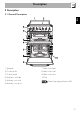
Description 2 Description EN 2.
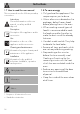
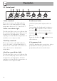
Description 2.2 Control panel 1 Main oven knob Allows you to turn on the light inside the main oven or set a fan-assisted cooking temperature between 50°C and 245°C. 2 Main oven indicator light The indicator light comes on to indicate that the oven is heating up. It turns off as soon as it reaches the set temperature. It flashes regularly to indicate that the temperature set inside the oven is kept constant.
Description EN 2.3 Cooking hob AUX = Auxiliary SR = Semi-rapid UR2 = Ultra-rapid 2.4 Other parts Shelves Cooling fan The appliance features shelves to position trays and racks at different heights. The insertion heights are indicated from the bottom upwards (see 2.1 General Description). The fan cools the ovens and comes into operation during cooking.
Description 2.5 Available accessories Tray Some models are not provided with all accessories. Rack Useful for collecting fat from foods placed on the rack above and for cooking pies, pizzas and baked desserts. Ring reducers Useful when using small cookware. WOK ring Useful for supporting containers with food during cooking. Tray rack Useful when using a wok. The accessories intended to come into contact with food are made of materials that comply with the provisions of current legislation.
Use 3.1 Instructions Improper use Danger of burns • Make sure that the flame-spreader crowns are correctly positioned in their housings with their respective burner caps. • Oils and fats could catch fire if overheated. Be very careful. High temperature inside the oven during use Danger of burns • Keep the oven door closed during cooking. • Protect your hands by wearing oven gloves when moving food inside the oven. • Do not touch the heating elements in the oven.
Use Improper use Risk of damage to surfaces • Do not cover the bottom of the oven cavity with aluminium or tin foil sheets. • If you wish to use greaseproof paper, place it so that it will not interfere with the hot air circulation inside the oven. • Do not place pans or trays directly on the bottom of the oven cavity. • Do not use the open door to rest pans or trays on the internal glass pane. • Do not pour water directly onto very hot trays.
Racks and trays Ring reducers Racks and trays have to be inserted into the side guides until they come to a complete stop. • The mechanical safety locks that prevent the rack from being taken out accidentally have to face downwards and towards the oven back. The ring reducers have to be placed on the hob grids. Make sure they are properly placed. Gently insert racks and trays into the oven until they come to a stop.
Use 3.4 Using the hob All the appliance’s control and monitoring devices are located together on the front panel. The burner controlled by each knob is shown next to the knob. The appliance is equipped with an electronic ignition device. Simply press the knob and turn it anticlockwise to the maximum flame symbol, until the burner lights. If the burner does not light in the first 15 seconds, turn the knob to and wait 60 seconds before trying again.
Use Switching on the main oven To switch on the main oven: • Turn the knob clockwise to select the required temperature between 50°C and 245°C. Switching on the auxiliary oven To switch on the auxiliary oven: • Turn the knob clockwise to select the required temperature between 50°C and 245°C. • Turn the knob clockwise further to select on the available functions at maximum temperature.
Use 64 Small grill Using only the heat released from the central element, this function allows you to grill small portions of meat and fish for making kebabs, toasted sandwiches and any types of grilled vegetable side dishes. 3.6 Cooking advice Grill The heat coming from the grill element gives perfect grilling results above all for thin and medium thickness meat and, in combination with the rotisserie (where fitted), gives the food an even browning at the end of cooking.
• Foods should be seasoned before cooking. Foods should also be coated with oil or melted butter before cooking. • Use the tray on the first bottom shelf to collect liquids produced by grilling. • Grilling processes should never last more than 30 minutes inside the auxiliary oven. Advice for cooking desserts/pastries and biscuits • Use dark metal moulds: They help to absorb the heat better. • The temperature and the cooking time depend on the quality and consistency of the dough.
Use 3.7 Programmer clock Setting the time If the time is not set, the oven will not switch on. On the first use, or after a power failure, the digits will be flashing on the appliance's display. 1. Press the keys and at the same time. The dot between the hours and the minutes flashes. 1 Minute minder timer key 2 Cooking duration key 3 End of cooking key 4 Value decrease key 5 Value increase key The programmer clock only controls the main oven and does not control the auxiliary oven.
Use Timed cooking is the function which allows a cooking operation to be started and then ended after a specific length of time set by the user. 1. After selecting a cooking function and temperature, press the key . The display will show the digits and the symbol displayed between the hours and the minutes. 2. Use the key or to set the required minutes. 3. Wait approx. 5 seconds without pressing any key in order for the function to activate. The current time and the symbols and will appear on the display.
Use 4. Wait approx. 5 seconds without pressing any key in order for the function to activate. The current time and the symbols and will appear on the display. 5. At the end of cooking the heating elements will be deactivated. On the display, the symbol turns off, the symbol flashes and the buzzer sounds. 6. To turn off the buzzer just press any key of the programmer clock. 7. Press the keys and at the same time to reset the programmer clock.
Use Weight (Kg) Function Runner position from the bottom Temperature (°C) Time (minutes) Roast veal 2 Circulaire 2 180 - 190 90 - 100 Pork 2 Circulaire 2 180 - 190 70 - 80 Roast beef 1 Circulaire 2 200 40 - 45 Roast rabbit 1.5 Circulaire 2 180 - 190 70 - 80 Food Turkey breast 3 Circulaire 2 180 - 190 110 - 120 Roast pork neck 2-3 Circulaire 2 180 - 190 170 - 180 Roast chicken 1.2 Circulaire 2 180 - 190 65 - 70 Salmon trout 1.
Use Auxiliary oven cooking information table Runner Temperature position from (°C) the bottom Weight (Kg) Function Lasagne 3-4 Static 1 220 - 230 45 - 50 Pasta bake 3-4 Static 1 220 - 230 45 - 50 1 Static 1 245 14 - 16 Food Pizza Time (minutes) Savoury spinach pie 1.2 Static 1 220 - 230 35 - 40 Focaccia 0.8 Static 1 190 - 200 18 - 20 1 Static 1 170 - 180 35 - 40 Short pastry 0.4 Static 1 170 - 180 20 - 25 Short pastry biscuits 0.
4 Cleaning and maintenance Cleaning the hob grids, flame-spreader crowns and burner caps 4.1 Instructions 1. Remove the components from the hob. 2. Clean it with warm water and nonabrasive detergent. Make sure to remove any encrustations. 3. Dry thoroughly with a soft cloth or a microfibre cloth. Improper use Risk of damage to surfaces • Do not use steam jets to clean the appliance. • Do not use detergents which are abrasive, corrosive or which contain chlorine, ammonia or bleach (e.g.
Cleaning and maintenance Recommendations for cleaning the oven compartment In order to keep your oven in the best possible condition, clean it regularly after letting it cool down. Avoid letting food residue dry inside the oven compartment, as this could damage the enamel. Take out all removable parts before cleaning.
Cleaning and maintenance 3. Remove the intermediate glass pane by lifting it upwards. EN 1. Remove the internal glass pane by pulling the rear part gently upwards, following the movement indicated by the arrows (1). 2. Then, pull the front part upwards (2). In this way, the 4 pins attached to the glass detach from their housings in the oven door. 4. Clean the external glass pane and the panes previously removed. Use absorbent kitchen roll.
Cleaning and maintenance 5. Refit the panes in the reverse order in which they were removed. 6. Reposition the internal glass pane. Take care to centre and insert the 4 pins into their housings in the oven door by applying slight pressure. When cleaning is complete, repeat the above procedures to put the rack/tray support frames back in. 4.5 Extraordinary maintenance Removing and installing the seal To remove the seal: • Unhook the clips in the 4 corners then pull the seal outwards.
Cleaning and maintenance Replacing the oven light bulb 4. Slide out and remove the lamp. EN Live parts Danger of electrocution • Disconnect the appliance from the power supply. The oven is fitted with a 40W light bulb. 1. Completely remove all accessories from inside the oven. 2. Remove the rack/tray support frames. 3. Remove the bulb cover using a tool (e.g. a screwdriver). Do not touch the halogen lamp directly with your fingers, but wrap it in insulating material. 5. Fit the new light bulb. 6.
Installation 5 Installation 5.1 Gas connection Gas leak Danger of explosion • After carrying out any operation, check that the tightening torque of gas connections is between 10 Nm and 15 Nm. • If required, use a pressure regulator that complies with current regulations. • At the end of the installation, check for any leaks with a soapy solution, never with a flame.
Installation Carefully screw the connector (3) to the gas connector (1) of the appliance, placing the seal (2) between them. EN Carefully screw the hose connector 3 to the appliance’s gas connector (1) (½” thread ISO 228-1), placing the seal (2) between them. The hose connector (4) can also be screwed to the hose connector (3), depending on the diameter of the gas hose used.
Installation Connection with a steel hose with conical fitting Make the connection to the gas mains using a continuous wall steel hose whose specifications comply with the applicable standard. Carefully screw the hose connector 3 to the appliance’s gas connector (1) (½” thread ISO 228-1), placing the supplied seal (2) between them. Apply insulating material to the thread of connector (3), then tighten the steel hose (4) to the connector (3).
Installation 5.2 Adaptation to different types of gas In case of operation with other types of gas, the burner nozzles must be changed and the minimum flame adjusted on the gas taps. Replacing nozzles 1. Remove the grids, burner caps and flame-spreader crowns to access the burner casings. 2. Replace the nozzles using a 7 mm socket wrench according to the gas to be used (see Burner and nozzle characteristics tables).
Installation Adjusting the minimum setting for natural or town gas Light the burner and turn it to the minimum position. Extract the gas tap knob and turn the adjustment screw next to the tap rod (depending on the model) until the correct minimum flame is achieved. Refit the knob and verify that the burner flame is stable. Turn the knob rapidly from the maximum to the minimum setting: The flame should not go out. Repeat the operation on all gas taps.
Installation Gas types and Countries 1 Natural Gas G20 G20 20 mbar G20/25 20/25 mbar 2 Natural Gas G25.3 G25.3 25 mbar 3 Natural Gas G25 G25 20 mbar 4 Natural Gas G2.350 G2.
Installation 4 Natural Gas G2.
Installation Power voltage Danger of electrocution • Have the electrical connection performed by authorised technical personnel. • Use personal protective equipment. • The appliance must be connected to earth in compliance with electrical system safety standards. • Disconnect the mains supply. • Do not pull the cable to remove the plug. • Use cables withstanding a temperature of at least 90°C. • The tightening torque of the screws of the terminal board conductors must be 1.5 - 2 Nm.
Installation Fixed connection Fit the power line with an all-pole disconnection switch, with a clearance between its contacts that allows the complete disconnection as per the overvoltage category III, in compliance with the installation regulations. 3. Proceed with installation of the power supply cable. Access to the terminal board To connect the power supply cable, you must access the terminal board on the rear casing: 1. Remove the screws fastening the plate to the rear casing.
Installation Heavy appliance Crushing hazard Depending on the type of installation, this appliance belongs to classes: EN 5.4 Positioning • Position the appliance into the cabinet cutout with the help of a second person. Pressure on the open door Risk of damage to the appliance • Never use the oven door to lever the appliance into place when fitting. • Avoid exerting too much pressure on the oven door when open.
Installation 1. Loosen the 3 screws on the back of the top (A) and unscrew the 2 screws (B) on the side part of the upstand. C - Class 2 subclass 1 (Built-in appliance) The appliance must be installed by a qualified technician and according to the regulations in force. Assembling the upstand The upstand provided is an integral part of the product; it must be fastened to the appliance prior to installation. The upstand must always be positioned and secured correctly on the appliance. 86 2.
Installation The toe skirt provided is an integral part of the product; it must be fastened to the appliance prior to installation. The toe skirt must always be positioned and secured correctly on the appliance. 1. Place the toe skirt in the front bottom part of the appliance. 2. Screw the two side screws to fasten the toe skirt to the appliance. 3. Cover the holes of the toe skirt with the plugs provided.
Installation 5.5 Instructions for the installer • The plug must be accessible after installation. Do not bend or trap the power cable. • The appliance must be installed according to the installation diagrams. • Do not try to unscrew or force the threaded elbow of the fitting. You may damage this part of the appliance, which may void the manufacturer’s warranty. • Use soap and water to check for gas leaks on all connections. DO NOT use naked flames when looking for leaks.