Contents 1.1 1.2 1.3 1.4 1.5 1.6 1.7 4 General safety instructions Manufacturer liability This user manual Appliance purpose Identification plate Disposal How to read the user manual 2 Description 2.1 2.2 2.3 2.4 2.5 General Description Cooking hob Control panel Other parts Available accessories Cleaning the hob Cleaning the doors Cleaning the oven cavities Extraordinary maintenance 5 Installation 5.1 5.2 5.3 5.4 5.
Instructions 1 Instructions 1.1 General safety instructions Risk of personal injury • During use the appliance and its accessible parts become very hot. Never touch the heating elements during use. • Protect your hands by wearing oven gloves when moving food inside the oven. • Never try to put out a fire or flames with water: turn off the appliance and smother the flames with a fire blanket or other appropriate cover.
• Do not insert pointed metal objects (cutlery or utensils) into the slots in the appliance. • Do not pour water directly on very hot trays. • Keep the oven door closed during cooking. • If you need to move food or at the end of cooking, open the door 5 cm for a few seconds, let the steam come out, then open it fully. • Do not open the storage compartment (where present) when the oven is on and still hot. • The items inside the storage compartment could be very hot after using the oven.
Instructions • Racks and trays should be inserted as far as they will go into the side guides. The mechanical safety locks that prevent them from being removed must face downwards and towards the back of the oven. • Do not sit on the appliance. • Do not use steam jets to clean the appliance. • Do not obstruct ventilation openings and heat dispersal slots. • Never leave the appliance unattended during cooking operations where fats or oils could overheat and take fire.
• Do not use cleaning products containing chlorine, ammonia or bleach on parts made of steel or that have metallic surface finishes (e.g. anodizing, nickel- or chromium-plating). • Do not use abrasive or corrosive detergents (e.g. scouring powders, stain removers and metallic sponges) on glass parts. • Do not wash the removable components such as the hob grids, flame-spreader crowns and burner caps in a dishwasher. • Never use the oven door to lever the appliance into place when fitting.
Instructions • Before installation, make sure that the local distribution conditions (nature and pressure of the gas) and the adjustment of the appliance are compatible; • The adjustment conditions for this appliance are shown on the gas setting label. • This appliance is not connected to an exhaust system for combustion products. It must be installed and connected in compliance with the current installation regulations.
1.6 Disposal This appliance must be disposed of separately from other waste (Directives 2002/95/EC, 2002/96/EC, 2003/108/EC). The appliance does not contain substances in quantities sufficient to be considered hazardous to health and the environment, in accordance with current European directives. To dispose of the appliance: • Cut the power supply cable and remove it along with the plug. Power voltage Danger of electrocution • Disconnect the mains power supply. • Unplug the appliance.
Instructions 1.7 How to read the user manual This user manual uses the following reading conventions: Instructions General information on this user manual, on safety and final disposal. Description Description of the appliance and its accessories. Use Information on the use of the appliance and its accessories. Cleaning and maintenance Information for proper cleaning and maintenance of the appliance. Installation Information for the qualified technician: Installation, operation and inspection.
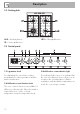
Description EN 2 Description 2.
Description 2.2 Cooking hob AUX = Auxiliary burner SR = Semi-rapid burner UR2 = Ultra-rapid burner 2.3 Control panel 1 Programmer clock 3 Multifunction oven indicator light For displaying the current time, setting programmed cooking operations and the minute minder timer. The indicator light comes on to indicate that the oven is heating up. It turns off as soon as it reaches the set temperature. It flashes regularly to indicate that the temperature set inside the oven is kept constant.
4 Multifunction oven temperature knob 2.4 Other parts This knob allows you to select the cooking temperature and the Vapor Clean temperature. Turn the knob clockwise to the required value, between the minimum and maximum setting. Shelves 5 Auxiliary oven knob Allows you to turn on the light inside the oven, set a static cooking temperature of between 50°C and 245°C, or select one of the other functions at maximum temperature.
Description 2.5 Available accessories Rack Tray rack To be placed over the top of the tray; for cooking foods which may drip. Useful for supporting containers with food during cooking. Rack Deep tray Useful for collecting fat from foods placed on the rack above and for cooking pies, pizzas and baked desserts. Useful for supporting containers with food during cooking. Tray Useful for collecting fat from foods placed on the rack above.
Description EN Ring reducer Useful when using small cookware. WOK ring Useful when using a wok. The accessories intended to come into contact with food are made of materials that comply with the provisions of current legislation. Supplied and optional accessories can be requested to Authorised Assistance Centres. Use only original accessories supplied by the manufacturer.
Use 3 Use Instructions Improper use Risk of damage to surfaces • Do not cover the bottom of the oven cavity with aluminium or tin foil sheets. • If you wish to use greaseproof paper, place it so that it will not interfere with the hot air circulation inside the oven. • Do not place pans or trays directly on the bottom of the oven cavity. • Do not use the open door to rest pans or trays on the internal glass pane. • Do not pour water directly onto very hot trays.
Precautions First use A gas leak can cause an explosion. 1. Remove any protective film from the outside or inside of the appliance, including accessories. 2. Remove any labels (apart from the technical data plate) from the accessories and from the oven cavity. 3. Remove and wash all the appliance's accessories (see 4 Cleaning and maintenance). 4. Heat the empty oven at the maximum temperature to burn off any residues left by the manufacturing process.
Use 3.2 Using the accessories Racks and trays Ring reducers Racks and trays have to be inserted into the side guides until they come to a complete stop. • The mechanical safety locks that prevent the rack from being taken out accidentally have to face downwards and towards the oven back. The ring reducers must be placed on the hob grids. Make sure they are placed properly. Tray rack The tray rack has to be inserted into the tray.
Use All the appliance’s control and monitoring devices are located together on the front panel. The burner controlled by each knob is shown next to the knob. The appliance is equipped with an electronic ignition device. Simply press the knob and turn it counterclockwise to the maximum flame symbol, until the burner ignites. If the burner does not light in the first 15 seconds, turn the knob to and wait 60 seconds before trying again.
Use 3.4 Using the ovens Switching on the multifunction oven To switch on the multifunction oven: 1. Select the cooking function using the function knob. 2. Select the temperature using the temperature knob. Multifunction oven functions Static As the heat comes from above and below at the same time, this system is particularly suitable for certain types of food. Traditional cooking, also known as static cooking, is suitable for cooking just one dish at a time.
Use Fan with round heating element The combination of the fan and the round heating element (incorporated in the rear of the oven) allows you to cook different foods on several levels, as long as they need the same temperatures and same type of cooking. Hot air circulation ensures instant and even distribution of heat. It will be possible, for instance, to cook fish, vegetables and biscuits simultaneously (on different levels) without odours and flavours mingling.
Use Auxiliary oven functions Static As the heat comes from above and below at the same time, this system is particularly suitable for certain types of food. Traditional cooking, also known as static cooking, is suitable for cooking just one dish at a time. Perfect for all types of roasts, bread and cakes and in any case particularly suitable for fatty meats such as goose and duck.
Use Advice for defrosting and proving 3.5 Programmer clock EN • The temperature and the cooking time depend on the quality and consistency of the dough. • When cooking on multiple levels, food should ideally be positioned on the second and fourth shelves; increase cooking time by a few minutes and only used fan functions. • To check whether the dessert is cooked right through: At the end of the cooking time, put a toothpick into the highest point of the dessert.
Use Timed cooking Setting the time If the time is not set, the oven will not switch on. On the first use, or after a power failure, the digits will be flashing on the appliance’s display. 1. Hold down the clock key for two seconds. The dot between the hours and the minutes flashes. 2. The time can be set via the value increase key and value decrease key . Keep the key pressed in to increase or decrease rapidly. 3. Wait 7 seconds. The dot between the hours and the minutes stops flashing. 4.
Use to reset the It is not possible to set a cooking time of more than 10 hours. To cancel the set programming press and hold down the value increase and the value decrease keys at the same time and then turn the oven off manually. 4. Use the or key to set the required minutes. (for example 1 hour) 5. Press the menu key 1. Set the cooking time as described in the previous point “Timed cooking”. 2. Hold the menu key 2 seconds. down for 3. Press the menu key again.
Use 10. Return the function and temperature knobs to 0. 11. To turn off the buzzer just press any key of the programmer clock. 12. Press the and keys at the same time to reset the set program. It is not possible to set a cooking time of more than 10 hours. It is not possible to set a programmed cooking time of more than 24 hours. After setting, hold the menu key down for 2 seconds to display the cooking time remaining. Press the menu key again.
Use 1. Press the clock key EN Modifying the set data . 2. Use the value increase and value decrease keys to set the number of minutes required. Deleting the set data 1. Press the clock key . 2. Hold down the value increase and value decrease keys at the same time. 3. Then switch off the oven manually if cooking is in progress. Selecting the buzzer The buzzer can have 3 tones. 1. Hold down the value increase value decrease time. 2. Press the clock key and keys at the same . 3.
Use Multifunction oven cooking information table Weight (kg) Function Shelf Temperature (°C) Time (minutes) Lasagne Pasta bake 3-4 3-4 Static Static 1 1 220 - 230 220 - 230 45 - 50 45 - 50 Roasted veal Pork loin Sausages Roast beef Roast rabbit Turkey breast Roast pork neck Roast chicken 2 2 1.5 1 1.5 3 2-3 1.
Use Weight (kg) Function Shelf Temperature (°C) Time (minutes) Lasagne Pasta bake 3-4 2 Static/Lower Static/Lower 1 1 220 - 230 220 - 230 50 - 60 40 Pork chops Sausages Roast rabbit Turkey breast Roast chicken 1 1,5 1 1,5 1 Static/Lower Grill Static/Lower Static/Lower Static/Lower 1 1 1 1 1 180 - 190 260 180 - 190 180 - 190 190 - 200 70 - 80 13 - 15 70 - 80 80 - 90 55 - 60 Food EN Auxiliary oven cooking information table Pork chops Spare ribs Bacon Pork fillet Beef fillet 1 1,5 0,8 1,5
Cleaning and maintenance 4 Cleaning and maintenance Instructions Improper use Risk of damage to surfaces • Do not use steam jets to clean the appliance. • Do not use cleaning products containing chlorine, ammonia or bleach on parts made of steel or that have metallic surface finishes (e.g. anodizing, nickelor chromium-plating). • Do not use abrasive or corrosive detergents (e.g. scouring powders, stain removers and metallic sponges) on glass parts.
Cleaning and maintenance For easier cleaning, the flame-spreader crowns and the burner caps can be removed. Wash them in hot water and nonabrasive detergent. Carefully remove any encrustation, then wait until they are perfectly dry. Refit the flame-spreader crowns making sure that they are correctly positioned in their housings with their respective burner caps. Igniters and thermocouples For correct operation the igniters and thermocouples must always be perfectly clean.
Cleaning and maintenance To reassemble the door, put the hinges in the relevant slots on the front of the oven, making sure that the grooved sections A are resting completely in the slots. Lower the door and once it is in place remove the pins from the holes in the hinges. 3. Remove the intermediate glass pane by lifting it upwards. Cleaning the door glazing 1. Remove the internal glass pane by pulling the rear part gently upwards, following the movement indicated by the arrows (1). 2.
6. Reposition the internal glass pane. Take care to centre and insert the 4 pins into their housings in the oven door by applying slight pressure. Removing rack/tray support frames Removing the rack/tray support frames enables the sides to be cleaned more easily. To remove the rack/tray support frames, pull the frame towards the inside of the oven to unhook it from its groove A, then slide it out of the seats at the back B.
Cleaning and maintenance Cleaning the roof of the oven High temperature inside the oven during use Danger of burns • The following operations must be performed only with the oven switched off and completely cool. The appliance is equipped with a tilting grill element that allows for easy cleaning of the upper part of the oven cavity. 1. Free the upper heating element by gently lifting it and rotating its retaining latch by 90 degrees. 2. Gently lower the heating element until it stops.
• Spray a water and washing up liquid solution inside the oven using a spray nozzle. Direct the spray against the side walls, upwards, downwards and towards the deflector. • Close the door. We recommend spraying approx. 20 times at the most. Vapor Clean cycle setting End of the Vapor Clean cycle 4. Open the door and wipe away the less stubborn dirt with a microfibre cloth. 5. Use a non-scratch sponge with brass filaments on hard to remove deposits. 6.
Cleaning and maintenance 4.4 Extraordinary maintenance 4. Slide out and remove the lamp. Replacing the oven light bulb Live parts Danger of electrocution • Disconnect the appliance from the power supply. The oven is fitted with a 40W light bulb. 1. Completely remove all accessories from inside the oven. 2. Remove the rack/tray support frames. 3. Remove the bulb cover using a tool (e.g. a screwdriver). Do not touch the halogen lamp directly with your fingers, but wrap it in insulating material. 5.
Removing and installing the seal To remove the seal: • Unhook the clips in the 4 corners then pull the seal outwards. To refit the seal: • Hook the clips in the 4 corners onto the seal. Seal maintenance tips The seal should be soft and elastic. • To keep the seal clean, use a nonabrasive sponge and lukewarm water to wash it. What to do if... The appliance does not work: • The switch is defective: check the fuse box and check that the switch is in order.
Installation 5 Installation 5.1 Gas connection (not valid for the UK) For installation in the UK, please refer to the “Local specifications for UK gas appliances installation” booklet. Gas leak Danger of explosion • After carrying out any operation, check that the tightening torque of gas connections is between 10 Nm and 15 Nm. • If required, use a pressure regulator that complies with current regulations. • At the end of the installation, check for any leaks with a soapy solution, never with a flame.
Carefully screw the hose connector 3 to the appliance’s gas connector 1 (½” thread ISO 228-1), placing the seal 2 between them. The hose connector 4 can also be screwed to the hose connector 3, depending on the diameter of the gas hose used. After having tightened the hose connector(s), push the gas hose 6 onto the hose connector and secure it with the clamp 5 that is compliant with the standard in force.
Installation Connection to LPG Room ventilation Use a pressure regulator and make the connection on the gas cylinder following the guidelines set out in the standards in force. The appliance should be installed in rooms that have a permanent air supply in accordance with the standards in force. The room where the appliance is installed must have enough air flow for the regular combustion of gas and the necessary air change in the room itself.
5.2 Adaptation to different types of gas In case of operation with other types of gas, the burner nozzles must be changed and the minimum flame adjusted on the gas taps. Replacing nozzles 1. Remove the grids, burner caps and flame-spreader crowns in order to access the burner cups.
Installation Adjusting the minimum setting for LPG Tighten the screw located at the side of the cock rod clockwise all the way. Following adjustment to a gas other than the one originally set in the factory, replace the gas setting label on the appliance with the one corresponding to the new gas. The label is inserted inside the nozzle pack (where present). Lubricating the gas taps 3. Reposition the burners in their respective housings.
Gas types and Countries IT GB-IE FR-BE DE AT NL ES PT SE RU DK PL HU Gas types 1 Natural gas G20 G20 20 mbar • • • • • • • • • • • G20/25 20/25 mbar 2 Natural gas G20 G20 • 25 mbar 3 Natural gas G25 G25 25 mbar G25.3 25 mbar • • 4 Natural gas G25.1 G25.
Installation Burner and nozzle characteristics tables 1 Natural gas G20 - 20 mbar Rated heating capacity (kW) Nozzle diameter (1/100 mm) Pre-chamber (printed on nozzle) Reduced flow rate (W) 2 Natural gas G20 - 25 mbar Rated heating capacity (kW) Nozzle diameter (1/100 mm) Pre-chamber (printed on nozzle) Reduced flow rate (W) 3 Natural gas G25/G25.3 - 25 mbar Rated heating capacity (kW) Nozzle diameter (1/100 mm) Pre-chamber (printed on nozzle) Reduced flow rate (W) 4 Natural gas G25.
7 LPG G30/31 - 30/37 mbar Rated heating capacity (kW) Nozzle diameter (1/100 mm) Pre-chamber (printed on nozzle) Reduced flow rate (W) Rated flow rate G30 (g/h) Rated flow rate G31 (g/h) 8 LPG G30/31 - 37 mbar Rated heating capacity (kW) Nozzle diameter (1/100 mm) Pre-chamber (printed on nozzle) Reduced flow rate (W) Rated flow rate G30 (g/h) Rated flow rate G31 (g/h) 9 LPG G30/31 - 50 mbar Rated heating capacity (kW) Nozzle diameter (1/100 mm) Pre-chamber (printed on nozzle) Reduced flow rate (W) Rated flo
Installation 5.3 Positioning Heavy appliance Crushing hazard • Position the appliance into the cabinet cut-out with the help of a second person. Pressure on the open door Risk of damage to the appliance • Never use the oven door to lever the appliance into place when fitting. • Avoid exerting too much pressure on the door when open. Any wall units positioned above the worktop of the appliance must be at a minimum distance of at least Y mm.
Installation B - Class 2 subclass 1 (Built-in appliance) A 600 mm B 600 mm C1 D min. 150 mm 900 - 915 mm H 750 mm I 450 mm L2 600 mm EN Appliance overall dimensions 1 Minimum distance from side walls or other flammable material. 2 Minimum cabinet width (=A). C - Class 2 subclass 1 (Built-in appliance) The appliance must be installed by a qualified technician and according to the regulations in force.
Installation Dimensions of the appliance: locations of gas and electric connections (mm) Positioning and levelling Heavy appliance Risk of damage to the appliance • Insert the front feet first and then the rear ones. The appliance must sit level on the floor to ensure stability. • After making the gas and electrical connections, level and stabilise the appliance on the floor by screwing the foot in or out.
General information 4. Secure the upstand to the hob by tightening the 4 screws previously loosened. 5.4 Electrical connection Check the grid characteristics against the data indicated on the plate. The identification plate bearing the technical data, serial number and brand name is visibly positioned on the appliance. Do not remove this plate for any reason. Perform the ground connection using a wire that is 20 mm longer than the other wires.
Installation • 220-240 V 3~ 4 x 1.5 mm² four-core cable. • 380-415 V 3N~ 5 x 1.5 mm² five-core cable. The values indicated above refer to the cross-section of the internal conductor. The aforementioned power cables are sized taking into account the coincidence factor (in compliance with standard EN 60335-2-6).