Table of contents 1.1 1.2 1.3 1.4 1.5 1.6 1.7 4 General safety instructions Manufacturer liability Appliance purpose Identification plate This user manual Disposal How to read the user manual 2 Description 2.1 2.2 2.3 2.4 2.5 General Description Cooking hob Control panel Other parts Available accessories Instructions Cleaning the surfaces Cleaning the hob Cleaning the door Cleaning the oven cavity Extraordinary maintenance 5 Installation 5.1 5.2 5.3 5.4 5.
Instructions 1 Instructions 1.1 General safety instructions Risk of personal injury • During use the appliance and its accessible parts become very hot. Never touch the heating elements during use. • Protect your hands by wearing oven gloves when moving food inside the oven. • Never try to put out a fire or flames with water: turn off the appliance and smother the flames with a fire blanket or other appropriate cover.
• While cooking do not place metal objects, such as cutlery or dishes on the hob surface as they may overheat. • Do not insert pointed metal objects (cutlery or utensils) into the slots in the appliance. • Do not pour water directly on very hot trays. • Keep the oven door closed during cooking. • If you need to move food or at the end of cooking, open the door 5 cm for a few seconds, let the steam come out, then open it fully.
Instructions Risk of damaging the appliance • Do not use abrasive or corrosive detergents (e.g. scouring powders, stain removers and metallic sponges) on glass parts. • Use wooden or plastic utensils. • Racks and trays should be inserted as far as they will go into the side guides. The mechanical safety locks that prevent them from being removed must face downwards and towards the back of the oven. • Do not sit on the appliance. • Do not use steam jets to clean the appliance.
• All pans must have smooth, flat bottoms. • If any liquid does boil over or spill, remove the excess from the hob. • Take care not to spill acid substances such as lemon juice or vinegar on the hob. • Do not put empty pans or frying pans on switched on cooking zones. • Do not use steam jets to clean the appliance. • Do not use rough or abrasive materials or sharp metal scrapers.
Instructions • Installation using a hose must be carried out so that the length of the hose does not exceed 2 metres when fully extended for steel hoses and 1.5 metres for rubber hoses. • The hoses should not come into contact with moving parts and should not be crushed in any way. • If required, use a pressure regulator that complies with current regulations. • After carrying out any operation, check that the tightening torque of gas connections is between 10 Nm and 15 Nm.
1.3 Appliance purpose • This appliance is intended for cooking food in the home environment. Every other use is considered inappropriate. • The appliance is not designed to operate with external timers or with remote-control systems. 1.4 Identification plate The identification plate bears the technical data, serial number and brand name of the appliance. Do not remove the identification plate for any reason. 1.
Instructions • Deliver the appliance to the appropriate recycling centre for electrical and electronic equipment waste, or return it to the retailer when purchasing an equivalent product, on a one for one basis. Our appliances are packaged in non-polluting and recyclable materials. • Deliver the packing materials to the appropriate recycling centre. Plastic packaging Danger of suffocation • Do not leave the packaging or any part of it unattended. • Do not let children play with the plastic bags. 1.
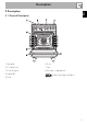
Description EN 2 Description 2.
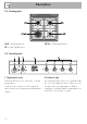
Description 2.2 Cooking hob AUX = Auxiliary burner SR = Semi-rapid burner UR-3c = Ultra-rapid burner 2.3 Control panel 1 Temperature knob 2 Indicator light This knob allows you to select the cooking temperature. Turn the knob clockwise to the required value, between the minimum and maximum setting. The indicator light comes on to indicate that the oven is heating up. It turns off as soon as it reaches the set temperature.
Description EN Cooling fan 3 Function knob The oven’s various functions are suitable for different cooking modes. After selecting the required function, set the cooking temperature using the temperature knob. 4 Programmer clock (on some models only) Useful for displaying the current time, setting programmed cooking operations and programming the minute minder timer. Intermediate positions between the figures can be used. The minute minder timer only activates the buzzer, without stopping cooking.
Description 2.5 Available accessories Ring reducer Rack Useful when using small cookware. WOK support Useful for supporting containers with food during cooking. Deep tray Useful when using a wok. Not all accessories are available on some models. Useful for collecting fat from foods placed on the rack above and for cooking pies, pizzas and baked desserts. 14 The oven accessories intended to come into contact with food are made of materials that comply with the provisions of current legislation.
Use 3.1 Instructions High temperature inside the oven during use Danger of burns • Keep the oven door closed during cooking. • Protect your hands wearing heat resistant gloves when moving food inside the oven. • Do not touch the heating elements inside the oven. • Do not pour water directly on very hot trays. • Keep children under the age of 8 away from the oven when it is in use.
Use High temperature inside the storage compartment Danger of fire or explosion • Do not spray any spray product near the appliance. • Do not use or leave flammable materials near the appliance or the storage compartment. • Do not use plastic cookware or containers for cooking. • Do not place sealed tins or containers in the oven cavity. • Do not leave the appliance unattended during cooking operations where fats and oils could be released. • Remove all trays and racks which are not required during cooking.
3.2 Using the accessories Racks and trays Ring reducers Racks and trays have to be inserted into the side guides until they come to a complete stop. • The mechanical safety locks that prevent the rack from being taken out accidentally have to face downwards and towards the oven back. The ring reducers must be placed on the hob grids. Make sure they are placed properly. Tray rack The tray rack has to be inserted into the tray.
Use 3.3 Using the hob All the appliance’s control and monitoring devices are located together on the front panel. The burner controlled by each knob is shown next to the knob. The appliance is equipped with an electronic ignition device. Simply press the knob and turn it counterclockwise to the maximum flame symbol, until the burner ignites. If the burner does not light in the first 15 seconds, turn the knob to and wait 60 seconds before trying again.
3.4 Using the oven Switching on the oven To switch the oven on: 1. Select the cooking function using the function knob. 2. Select the temperature using the temperature knob. Ensure that the programmer clock shows the cooking duration symbol , otherwise it will not be possible to turn on the oven. Press the keys and at the same time to reset the programmer clock. Functions list Static As the heat comes from above and below at the same time, this system is particularly suitable for certain types of food.
Use Fan with round heating element The combination of the fan and the round heating element (incorporated in the rear of the oven) allows you to cook different foods on several levels, as long as they need the same temperatures and same type of cooking. Hot air circulation ensures instant and even distribution of heat. It will be possible, for instance, to cook fish, vegetables and biscuits simultaneously (on different levels) without odours and flavours mingling.
Setting the time If the time is not set, the oven will not switch on. On the first use, or after a power failure, the digits will be flashing on the appliance’s display. 1. Press the keys and at the same time. The dot between the hours and the minutes flashes. 2. The time can be set using the key or . Keep the key pressed in to increase or decrease rapidly. 3. Press the key or wait 5 seconds. The dot between the hours and the minutes stops flashing. 2. Use the or key to set the required minutes. 3.
Use Programmed cooking Minute minder timer Programmed cooking is the function which allows a cooking operation to be started at a set time and then ended after a specific length of time set by the user. 1. Set the cooking time as described in the previous point “Timed cooking”. 2. Press the key. The sum of the current time plus the pre-set cooking duration will appear on the display. 3. Use the or key to set the required minutes. 4. Wait approx.
Deleting the set data 3.7 Cooking advice Press the keys and at the same time to reset the programs set. Then switch off the oven manually if cooking is in progress. General advice Adjusting the buzzer volume The buzzer volume can be set to 3 different levels. When the buzzer is in operation, press the key to change the setting. 3.6 Using the storage compartment The storage compartment is at the bottom of the cooker. To open it, pull the handle towards you.
Use • When using the Fan with grill function, we recommend that you preheat the oven before grilling. • We recommend placing the food at the centre of the rack. • With the Grill function, we recommend that you turn the temperature knob to the maximum value to optimise cooking. Advice for cooking desserts/pastries and biscuits • Use dark metal moulds: They help to absorb the heat better. • The temperature and the cooking time depend on the quality and consistency of the dough.
Use EN Cooking information table Weight (kg) Function Shelf Temperature (°C) Lasagne Pasta bake 3-4 3-4 Static Static 1 1 220 - 230 220 - 230 45 - 50 45 - 50 Roasted veal Pork loin Sausages Roast beef Roast rabbit Turkey breast Roast pork neck Roast chicken 2 2 1.5 1 1.5 3 2-3 1.
Cleaning and maintenance 4 Cleaning and maintenance 4.1 Instructions Improper use Risk of damage to surfaces • Do not use steam jets to clean the appliance. • Do not use cleaning products containing chlorine, ammonia or bleach on parts made of steel or that have metallic surface finishes (e.g. anodizing, nickelor chromium-plating). • Do not use abrasive or corrosive detergents (e.g. scouring powders, stain removers and metallic sponges) on glass parts.
4.3 Cleaning the hob Flame-spreader crowns and burner caps Knobs For easier cleaning, the flame-spreader crowns and the burner caps can be removed. Wash them in hot water and nonabrasive detergent. Carefully remove any encrustation, then wait until they are perfectly dry. Refit the flame-spreader crowns making sure that they are correctly positioned in their housings with their respective burner caps.
Cleaning and maintenance 4.4 Cleaning the door Removing the door For easier cleaning, the door can be removed and placed on a towel. To remove the door proceed as follows: 1. Open the door completely and insert two pins into the holes on the hinges indicated in the figure. 3. To reassemble the door, put the hinges in the relevant slots in the oven, making sure that grooved sections A are resting completely in the slots.
Removing the internal glass panes For easier cleaning, the internal glass panes of the door can be removed. 1. Remove the internal glass pane by pulling the rear part gently upwards following the movement indicated by the arrows (1). This way, the 4 pins attached to the glass detach from their housings in the door. 2. Then, pull the front part upwards (2). 3. Remove the intermediate glazing pane by lifting it upwards.
Cleaning and maintenance 4.5 Cleaning the oven cavity Cleaning of racks and trays For the best oven cavity upkeep, clean it regularly after having allowed it to cool. Avoid letting food residue dry inside the oven cavity, as this could damage the enamel. Take out all removable parts. Clean the racks and trays with warm water and non-abrasive detergents. Carefully rinse and dry damp parts.
Cleaning and maintenance EN Vapour Clean Vapor Clean is an assisted cleaning procedure which facilitates the removal of dirt. Thanks to this process, it is possible to clean the inside of the oven very easily. The dirt residues are softened by the heat and water vapour for easier removal afterwards. Improper use Risk of damage to surfaces • Remove any food residues or large spills from previous cooking operations from the inside of the oven.
Cleaning and maintenance Vapor Clean cycle setting 4.6 Extraordinary maintenance 1. Turn the function knob to the symbol and the temperature knob to the symbol Installing and removing the seal . 2. Set a cooking time of 18 minutes using the programmer clock. 3. At the end of the cooking time, the timer will switch the oven heating elements off and the buzzer will start to sound. To remove the seal: • Unhook the clips in the 4 corners then pull the seal outwards. End of the Vapor Clean cycle 4.
Cleaning and maintenance 4. Slide out and remove the light bulb. EN Replacing the internal light bulb Live parts Danger of electrocution • Unplug the appliance from the mains. • Wear protective gloves. 1. Remove all accessories from inside the oven cavity. 2. Remove the rack/tray support frames. 3. Remove the bulb cover using a tool (e.g. a screwdriver). Take care not to scratch the enamel of the oven cavity wall. Do not touch the halogen light bulb directly with your fingers, use an insulating material.
Installation 5 Installation 5.1 Gas connection (not valid for the UK) For installation in the UK, please refer to the “Local specifications for UK gas appliances installation” booklet. Gas leak Danger of explosion • After carrying out any operation, check that the tightening torque of gas connections is between 10 Nm and 15 Nm. • If required, use a pressure regulator that complies with current regulations. • At the end of the installation, check for any leaks with a soapy solution, never with a flame.
Carefully screw the hose connector 3 to the appliance’s gas connector 1 (½” thread ISO 228-1), placing the seal 2 between them. The hose connector 4 can also be screwed to the hose connector 3, depending on the diameter of the gas hose used. After having tightened the hose connector(s), push the gas hose 6 onto the hose connector and secure it with the clamp 5 that is compliant with the standard in force.
Installation Connection to LPG Room ventilation Use a pressure regulator and make the connection on the gas cylinder following the guidelines set out in the standards in force. The appliance should be installed in rooms that have a permanent air supply in accordance with the standards in force. The room where the appliance is installed must have enough air flow for the regular combustion of gas and the necessary air change in the room itself.
Installation EN 5.2 Adaptation to different types of gas In case of operation with other types of gas, the burner nozzles must be changed and the minimum flame adjusted on the gas taps. Replacing nozzles 1. Remove the grids, burner caps and flame-spreader crowns in order to access the burner cups.
Installation Adjusting the minimum setting for natural or town gas Light the burner and turn it to the minimum position. Remove the gas tap knob and turn the adjustment screw next to the tap rod (depending on the model) until the correct minimum flame is obtained. Refit the knob and verify that the burner flame is stable. Turn the knob rapidly from the maximum to the minimum setting: The flame should not go out. Repeat the operation on all gas cocks.
Installation Natural gas G20 - 20 mbar Rated heating capacity (kW) Nozzle diameter (1/100 mm) Pre-chamber (printed on nozzle) Reduced flow rate (W) LPG G30/31 - 30/37 mbar Rated heating capacity (kW) Nozzle diameter (1/100 mm) Pre-chamber (printed on nozzle) Reduced flow rate (W) Rated flow rate G30 (g/h) Rated flow rate G31 (g/h) AUX 1.05 72 (X) 400 AUX 1.05 50 400 76 75 SR 1.8 97 (Z) 500 SR 1.8 65 500 131 129 EN Burner and nozzle characteristics tables UR-3c 3.5 133 (S) 1600 UR-3c 3.
Installation 5.3 Positioning Heavy appliance Crushing hazard • Position the appliance into the cabinet cut-out with the help of a second person. Pressure on the open door Risk of damage to the appliance • Never use the oven door to lever the appliance into place when fitting. • Avoid exerting too much pressure on the door when open. Any wall units positioned above the worktop of the appliance must be at a minimum distance of at least Y mm.
Installation B - Class 2 subclass 1 (Built-in appliance) A 600 mm B 600 mm C1 D min. 150 mm 900 - 915 mm H 750 mm I 450 mm L2 600 mm EN Appliance overall dimensions 1 Minimum distance from side walls or other flammable material. 2 Minimum cabinet width (=A). C - Class 2 subclass 1 (Built-in appliance) The appliance must be installed by a qualified technician and according to the regulations in force.
Installation Dimensions of the appliance: locations of gas and electric connections (mm) Positioning and levelling Heavy appliance Risk of damage to the appliance • Insert the front feet first and then the rear ones. After making the electrical and/or gas connections, screw the four adjustable feet supplied with the appliance. A 124 B 32 C 42 D 628 F min. 105 - max.
Installation 3. Assemble the fastening bracket. EN Fastening to the wall The anti-tip devices must be installed in order to prevent the appliance from tipping over. 1. Screw the wall fastening plate to the rear of the appliance. 2. Adjust the height of the 4 feet. 4. Align the base of the hook on the fastening bracket with the base of the slot on the wall fastening plate.
Installation 5. Align the base of the fastening bracket with the ground and tighten the screws to fix the measurements. 6. Use 50 mm for the distance from the side of the appliance to the bracket holes. 44 7. Move the bracket onto the wall and mark the position of the holes to be drilled in the wall. 8. After drilling the holes in the wall, use wall plugs and screws to fasten the bracket to the wall. 9.
Installation The upstand provided is an integral part of the product. It must be fastened to the appliance prior to installation. The upstand must always be positioned and secured correctly on the appliance. 1. Unscrew the 2 nuts (B) on the back of the hob. 2. Position the upstand above the hob, taking care to align the pins (C) with the holes (D). 3. Secure the upstand to the hob by tightening the screws (A). 5.
Installation The appliance can work in the following modes: • 220-240 V 1N~ 3 x 1.5 mm² three-core cable. The values indicated above refer to the cross-section of the internal lead. The aforementioned power cables are sized taking into account the coincidence factor (in compliance with standard EN 60335-2-6). Fixed connection Fit the power line with an all-pole disconnection switch, with at least 3 mm between its contacts, in compliance with installation regulations.