Contents 1.1 1.2 1.3 1.4 1.5 1.6 1.7 General safety instructions Manufacturer liability Appliance purpose Disposal Identification plate This user manual How to read the user manual 2 Description 2.1 General Description 2.2 Burner knobs 3 Use 32 32 35 35 36 36 36 37 38 38 39 40 3.1 Instructions 3.2 First use 3.3 Using the hob 40 40 41 4 Cleaning and maintenance 44 4.1 Instructions 4.2 Cleaning the appliance 44 44 5 Installation 5.1 5.2 5.3 5.4 5.5 5.6 5.7 5.
Instructions 1 Instructions 1.1 General safety instructions Risk of personal injury • During use the appliance and its accessible parts become very hot. Never touch the heating elements during use. • Protect your hands by wearing oven gloves when moving food inside the oven. • Never try to put out a fire or flames with water: turn off the appliance and smother the flames with a fire blanket or other appropriate cover.
• While cooking do not place metal objects, such as cutlery or dishes on the hob surface as they may overheat. • Do not insert pointed metal objects (cutlery or utensils) into the slots in the appliance. • Do not pour water directly onto very hot trays. • Do not use aerosols in the vicinity of this appliance whilst it is in use. • Switch off the appliance immediately after use. • Do not modify this appliance. • Do not try to repair the appliance yourself or without the assistance of a qualified technician.
Instructions • Take care not to spill acid substances such as lemon juice or vinegar on the hob. • Do not put empty pans or frying pans on switched on cooking zones. • Do not use steam jets to clean the appliance. • Do not use rough or abrasive materials or sharp metal scrapers. • Do not use cleaning products containing chlorine, ammonia or bleach on parts made of steel or that have metallic surface finishes (e.g. anodizing, nickel- or chromium-plating). • Do not use abrasive or corrosive detergents (e.g.
Instructions 1.2 Manufacturer liability The manufacturer declines all liability for damage to persons or property caused by: • Use of the appliance other than the one envisaged, • failure to comply with the instructions in the user manual, • Tampering with any part of the appliance, • use of non-original spare parts. 1.3 Appliance purpose • This appliance is intended for cooking food in the home environment. Every other use is considered inappropriate.
Instructions 1.4 Disposal This appliance conforms to the WEEE European directive (2012/19/EU) and must be disposed of separately from other waste at the end of its service life. The appliance does not contain substances in quantities sufficient to be considered hazardous to health and the environment, in accordance with current European directives. To dispose of the appliance: Power voltage Danger of electrocution • Disconnect the mains power supply. • Unplug the appliance.
Instructions 1.7 How to read the user manual This user manual uses the following reading conventions: EN Instructions General information on this user manual, on safety and final disposal. Description Description of the appliance and its accessories. Use Information on the use of the appliance and its accessories. Cleaning and maintenance Information for proper cleaning and maintenance of the appliance. Installation Information for the qualified technician: Installation, operation and inspection.
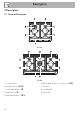
Description 2 Description 2.
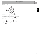
Description EN 2.2 Burner knobs For lighting and adjusting the hob burners. Press and turn anti-clockwise to in order to light the relative burners. Turn the knobs to the zone between the maximum and minimum setting to adjust the flame. Return the knobs to the position to turn off the burners.
Use 3 Use 3.1 Instructions Improper use Danger of burns • Make sure that the flame-spreader crowns are correctly positioned in their seats with their respective burner caps. • Oils and fats could catch fire if overheated. Be very careful. • Do not leave the appliance unattended during cooking operations where fats or oils could be released. • Do not spray any spray product near the appliance. • Do not touch the appliance’s heating elements when it is running. Leave them to cool before cleaning.
Use All the appliance’s control and monitoring devices are located together on the front panel. The burner controlled by each knob is shown next to the knob. The appliance is equipped with an electronic ignition device. Simply press the knob and turn it anticlockwise to the maximum flame symbol, until the burner ignites. If the burner does not light in the first 15 seconds, turn the knob to and wait 60 seconds before trying again.
Use Once the contents come to the boil, turn down the flame far enough to ensure that the liquid does not boil over. Cookware diameters: • AUX: 12 - 14 cm. • SR: 16 - 20 cm. • R: 22 - 26 cm. • UR2-UR3: 22 - 26 cm. To prevent burns or damage to the hob or the counter top during cooking, all cookware or griddles must be placed inside the perimeter of the hob.
Use EN A few precautions are necessary if you wish to use a griddle: • Griddles should be placed inside the perimeter of the hob and should not overlap this.
Cleaning and maintenance 4 Cleaning and maintenance 4.2 Cleaning the appliance 4.1 Instructions To keep the surfaces in good condition, they should be cleaned regularly after use. Let them cool first. Improper use Risk of damage to surfaces • Do not use steam jets to clean the appliance. • Do not use cleaning products containing chlorine, ammonia or bleach on parts made of steel or that have metallic surface finishes (e.g. anodizing, nickelor chromium-plating).
Cooking hob grids Igniters and thermocouples Remove the grids and clean them in lukewarm water and non-abrasive detergent. Make sure to remove any encrustations. Dry them thoroughly and return them to the hob. For correct operation the igniters and thermocouples must always be perfectly clean. Check them frequently and clean them with a damp cloth if necessary. Remove any dry residues with a wooden toothpick or a needle.
Installation 5 Installation 5.2 Section cut from the countertop The following operation requires building and/or carpentry work and must therefore be carried out by a competent tradesman. Installation can be carried out on various materials such as masonry, metal, solid wood or plastic laminated wood as long as they are heat resistant (>90 °C). 5.1 Safety instructions Heat production during appliance operation Risk of fire • Make sure that the cabinet material is heat resistant.
5.3 Mounting Over empty kitchen unit or drawers Over built-in oven unit If there are other pieces of furniture (lateral walls, drawers, etc.), dishwashers or fridges under the hob, a double-layer wooden base must be installed at least 10 mm from the bottom of the hob to avoid any accidental contact. It must only be possible to remove the double-layer base using suitable equipment.
Installation opens on rear Failure to install the double-layer wooden base exposes the user to possible accidental contact with sharp or hot parts. Hob seal 2. Use light pressure to make the seal stick to the edge around the hole cut in the worktop. 3. Carefully trim the surplus away from edge (C) beyond the seal. To prevent leakage of liquid between the frame of the hob and the work surface, place the insulating seal provided in position before assembly, as shown in the figure below. 1.
Installation Gas leak Danger of explosion • After carrying out any operation, check that the tightening torque of gas connections is between 10 Nm and 15 Nm. • If required, use a pressure regulator that complies with current regulations. • At the end of the installation, check for any leaks with a soapy solution, never with a flame. • The hoses should not come into contact with moving parts and should not be crushed in any way.
Installation Connection to LPG Use a pressure regulator and make the connection on the gas cylinder following the guidelines set out in the standards in force. The room must be kept adequately ventilated in order to eliminate the heat and humidity produced by cooking: In particular, after prolonged use, you are recommended to open a window or to increase the speed of any fans.
Installation 2. Remove the knobs lifting them from their housing. EN B Single chimney with extractor fan C Directly outdoors with wall- or windowmounted extractor fan D Directly outdoors through wall Air Combustion products Extractor fan 5.6 Adaptation to different types of gas If other types of gas are to be used, the nozzles must be replaced and the primary air must be adjusted. In order to replace the nozzles and adjust the burners, the hob top must be removed. 3.
Installation 5. Remove the gasket on each burner's thermocouple and igniter. 6. Remove the top. 2. Use a spanner to remove the nozzles “C” and install the new ones for the required gas supply, following the indications given in the relevant table (see “Gas types and Countries”). Replacing the nozzles/air regulation 3. Reposition support "B" so that nozzle “C” is covered completely. 1. Unscrew screw "A" and push air regulator "B" as far as it will go.
Installation Light the burner and turn it to the minimum position. Extract the gas cock knob and turn the adjustment screw next to the tap rod (depending on the model) until the correct minimum flame is achieved. Refit the knob and verify that the burner flame is stable. Turn the knob rapidly from the maximum to the minimum setting: The flame should not go out. Repeat the operation on all gas cocks. 4.
Installation Adjusting the minimum setting for LPG Tighten the screw located at the side of the tap rod clockwise all the way. Following adjustment to a gas other than the one originally set in the factory, replace the gas setting label on the appliance with the one corresponding to the new gas. The label is inserted inside the nozzle pack (where present). Lubricating the gas cocks Over time the gas taps may become difficult to turn and get blocked. Clean them internally and replace the lubrication grease.
Installation Gas types and Countries 1 Natural gas G20 G20 20 mbar G20/25 20/25 mbar 2 Natural gas G20 G20 25 mbar 3 Natural gas G25.1 G25.1 25 mbar 4 Natural gas G25 G25 20 mbar 5 Natural gas G2.350 G2.
Installation Burner and nozzle specifications tables 1 Natural gas G20 - 20 mbar Rated heating capacity (kW) Nozzle diameter (1/100 mm) Reduced flow rate (W) Primary air (mm) 2 Natural gas G20 - 25 mbar Rated heating capacity (kW) Nozzle diameter (1/100 mm) Reduced flow rate (W) Primary air (mm) 3 Natural gas G25.
8 LPG G30/31 - 50 mbar Rated heating capacity (kW) Nozzle diameter (1/100 mm) Reduced flow rate (W) Primary air (mm) Rated flow rate G30 (g/h) Rated flow rate G31 (g/h) 9 Town gas G110 – 8 mbar Rated heating capacity (kW) Nozzle diameter (1/100 mm) Reduced flow rate (W) Primary air (mm) AUX SR R UR2 (int + ext) UR3 1.10 48 400 2 80 79 AUX 1.70 54 450 2 124 121 SR 3.10 73 750 2 225 221 R 1.10 + 3.90 42 + 82 400 + 1400 2+5 80 + 284 79 + 279 UR2 (int + ext) 3.30 76 1400 2.5 240 236 UR3 1.
Installation The circuit breaker should be located near the appliance and in an easily reachable position. Connection with plug and socket Make sure that the plug and socket are of the same type. Avoid using adapters, gang sockets or shunts as these could cause overheating and a risk of burns. Testing At the end of installation, carry out a brief inspection test.