Contents 1.1 1.2 1.3 1.4 1.5 1.6 1.7 4 General safety instructions Manufacturer liability Appliance purpose Identification plate This user manual Disposal How to read the user manual 4 7 7 7 7 7 8 2 Description 2.1 General Description 2.2 Burner knobs 2.3 Available accessories 3 Use 3.1 3.2 3.3 3.4 9 9 9 10 11 Instructions First use Using the accessories Using the hob 11 11 12 12 4 Cleaning and maintenance 15 4.1 Instructions 4.2 Cleaning the appliance 15 15 5 Installation 5.1 5.2 5.3 5.4 5.
Instructions 1 Instructions 1.1 General safety instructions Risk of personal injury • During use the appliance and its accessible parts become very hot. Never touch the heating elements during use. • Never try to put out a fire or flames with water: turn off the appliance and smother the flames with a fire blanket or other appropriate cover.
• Do not pull the cable to remove the plug. • If the power supply cable is damaged, contact technical support immediately and they will replace it. Risk of damaging the appliance • Do not sit on the appliance. • Do not use steam jets to clean the appliance. • Do not obstruct ventilation openings and heat dispersal slots. • Never leave the appliance unattended during cooking operations where fats or oils could overheat and take fire. Be very careful. • Never leave objects on the cooking surface.
Instructions • Before performing any operation on the appliance, switch off the power supply. • Have qualified personnel carry out installation and assistance interventions according to the standards in force. • Have the gas connection performed by authorised staff. Installation with a hose must be carried out so that the length of the piping does not exceed 2 metres when fully extended (for steel hoses). • The hoses should not come into contact with moving parts and should not be crushed in any way.
1.2 Manufacturer liability The manufacturer declines all liability for damage to persons or property caused by: • use of the appliance other than the one envisaged, • failure to comply with the instructions in the user manual, • tampering with any part of the appliance, • use of non-original spare parts. 1.3 Appliance purpose This appliance is intended for cooking food in the home environment. Every other use is considered inappropriate. 1.
Instructions • Cut the power supply cable and remove it along with the plug. • Deliver the appliance to the appropriate recycling centre for electrical and electronic equipment waste, or return it to the retailer when purchasing an equivalent product, on a one for one basis. • Our appliances are packaged in non-polluting and recyclable materials. • Deliver the packing materials to the appropriate recycling centre.
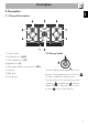
Description EN 2 Description 2.1 General Description 1 Control panel 2 Auxiliary burner (AUX) 3 Semi-rapid burner (SR) 4 Rapid burner (R) 5 Ultra-rapid double crown burner (UR2) 6 Left grid 7 Right grid 8 Central grid 2.2 Burner knobs Used for lighting and adjusting the hob burners. Press and turn anti-clockwise to in order to light the relative burners. Turn the knobs to the zone between the maximum and minimum setting to adjust the flame. Return the knobs to the position to turn off the burners.
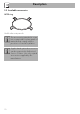
Description 2.3 Available accessories WOK ring Useful when using a wok. The accessories intended to come into contact with food are made of materials that comply with the provisions of current legislation. Supplied and optional accessories can be requested to Authorised Service Centres. Use only original accessories supplied by the manufacturer.
Use 3.1 Instructions Improper use Danger of burns • Make sure that the flame-spreader crowns are correctly positioned in their seats with their respective burner caps. • Oils and fats could catch fire if overheated. Be very careful. • Do not leave the appliance unattended during cooking operations where fats or oils could be released. • Do not spray any spray product near the appliance. • Do not touch the appliance’s heating elements when it is running. Leave them to cool before cleaning.
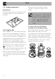
Use 3.3 Using the accessories Ring reducers The ring reducers have to be placed on the hob grids. Make sure they are placed properly. Wait a few moments and repeat the operation. Keep the knob pressed in longer. In case of an accidental switching off, a safety device will be tripped, cutting off the gas supply, even if the gas cock is open. Return the knob to and wait at least 60 seconds before lighting it again. Correct positioning of the flamespreader crowns and burner caps 3.
Practical tips for using the hob For better burner efficiency and to minimise gas consumption, use pans with lids and of suitable size for the burner, so that the flames do not reach up the sides of the pan. Once the contents come to the boil, turn down the flame far enough to ensure that the liquid does not boil over. Cookware diameters: • AUX: 12 - 14 cm. • SR: 16 - 20 cm. • R: 22 - 26 cm. • UR2: 22 - 26 cm.
Use A few precautions are necessary if you wish to use a griddle: • Griddles should be placed inside the perimeter of the hob and should not overlap this.
4 Cleaning and maintenance 4.2 Cleaning the appliance 4.1 Instructions To keep the surfaces in good condition, they should be cleaned regularly after use. Let them cool first. Improper use Risk of damage to surfaces • Do not use steam jets to clean the appliance. • Do not use cleaning products containing chlorine, ammonia or bleach on parts made of steel or that have metallic surface finishes (e.g. anodizing, nickelor chromium-plating).
Cleaning and maintenance Cooking hob grids Igniters and thermocouples Remove the grids and clean them in lukewarm water and non-abrasive detergent. Make sure to remove any encrustations. Dry them thoroughly and return them to the hob. For correct operation the igniters and thermocouples must always be perfectly clean. Check them frequently and clean them with a damp cloth if necessary. Remove any dry residues with a wooden toothpick or a needle.
5 Installation 5.2 Section cut from the countertop The following operation requires building and/or carpentry work and must therefore be carried out by a competent tradesman. Installation can be carried out on various materials such as masonry, metal, solid wood or plastic laminated wood as long as they are heat resistant (>90°C). 5.1 Safety instructions Heat production during appliance operation Risk of fire • Make sure that the cabinet material is heat resistant.
Installation 5.3 Mounting Over empty kitchen unit or drawers Over built-in oven unit If there are other pieces of furniture (lateral walls, drawers, etc.), dishwashers or fridges under the hob, a double-layer wooden base must be installed at least 10 mm from the bottom of the hob to avoid any accidental contact. It must only be possible to remove the double-layer base using suitable equipment.
Hob seal 5.4 Fixing to the supporting structure To prevent leakage of liquid between the frame of the hob and the work surface, place the insulating seal provided in position before assembly, as shown in the figure below. 1. Refer to the dimensions in the figure, bearing in mind that all the sides "A" of the seal must brush against the hole. Secure the hob to the piece of furniture through the appropriate bracket (A). Do not fix the hob using silicone.
Installation General information Connection to the gas mains can be made using a rigid copper pipe or a continuous wall steel hose in compliance with the provisions established by the applicable standard. The appliance is preset for natural gas G20 (2H) at a pressure of 20 mbar. For supplying it with other types of gas, see chapter “5.6 Adaptation to different types of gas”. The gas inlet connection is threaded ½” external gas (ISO 228-1). Apply insulating material (½” ISO 7.
Room ventilation This domestic appliance is not connected to a device for extracting combustion products. It must be installed and connected in accordance with current installation regulations. Pay particular attention to the relevant requirements regarding ventilation. The appliance should be installed in rooms that have a permanent air supply in accordance with the standards in force.
Installation 5.6 Adaptation to different types of gas 3. Remove the flame-spreader crowns and relative burner caps. If other types of gas are to be used, the nozzles must be replaced and the primary air must be adjusted. In order to replace the nozzles and adjust the burners, the hob top must be removed. Removing the hob top 1. Remove the grids from the hob. 4. Unscrew the screws under each burner to remove the fixing plate. 2. Remove the knobs lifting them from their housing. 5.
Installation EN 6. Remove the top. 3. Reposition support "B" so that nozzle "C" is covered completely. Replacing the nozzles/air regulation 1. Unscrew screw "A" and push air regulator "B" as far as it will go. 4. Move the Venturi tube "D" to adjust the air flow until distance "X" is reached as indicated in the paragraph (see Table "Burner and nozzle characteristics" "Primary air adjustment (mm)") and then secure the tube by means of screw "A". 5.
Installation Adjusting the minimum setting for natural or town gas Light the burner and turn it to the minimum position. Extract the gas cock knob and turn the adjustment screw next to the tap rod (depending on the model) until the correct minimum flame is achieved. Refit the knob and verify that the burner flame is stable. Turn the knob rapidly from the maximum to the minimum setting: The flame should not go out. Repeat the operation on all gas cocks.
Burner and nozzle specifications tables Natural gas G20 - 20 mbar Rated heating capacity (kW) Nozzle diameter (1/100 mm) Reduced flow rate (W) Primary air (mm) LPG G30/31 - 30/37 mbar Rated heating capacity (kW) Nozzle diameter (1/100 mm) Reduced flow rate (W) Primary air (mm) Rated flow rate G30 (g/h) Rated flow rate G31 (g/h) AUX SR R UR2 (int + ext) 1.10 73 400 1.5 AUX 1.7 92 450 1.5 SR 3.10 126 750 2.5 R 1.10 + 3.90 73 + 140 400 + 1200 2+3 UR2 (int + ext) 1.10 48 400 2 80 79 1.
Installation 5.7 Electrical connection Power voltage Danger of electrocution • Have the electrical connection performed by authorised technicians. • Use personal protective equipment. • The appliance must be connected to ground in compliance with electrical system safety standards. • Disconnect the mains power supply. • Do not pull the cable to remove the plug. • Use cables withstanding a temperature of at least 90°C. • The tightening torque of the screws of the terminal board leads must be 1.5 - 2 Nm.
Installation EN 5.8 Instructions for the installer • The plug must be accessible after installation. Do not bend or trap the power cable. • The appliance must be installed according to the installation diagrams. • Do not try to unscrew or force the threaded elbow of the fitting. You may damage this part of the appliance, which may void the manufacturer’s warranty. • Use soap and water to check for gas leaks on all connections. DO NOT use naked flames to find leaks.