Contents 1.1 1.2 1.3 1.4 1.5 1.6 1.7 General safety instructions Manufacturer liability Appliance purpose Identification plate This user manual Disposal How to read the user manual 2 Description 2.1 General Description 2.2 Burner knobs 2.3 Available accessories 3 Use 3.1 3.2 3.3 3.4 34 34 37 37 37 37 38 39 40 40 42 42 43 Instructions First use Using the accessories Using the hob 43 43 44 44 4 Cleaning and maintenance 47 4.1 Instructions 4.2 Cleaning the appliance 47 47 5 Installation 5.1 5.2 5.
Instructions 1 Instructions 1.1 General safety instructions Risk of personal injury • During use the appliance and its accessible parts become very hot. Never touch the heating elements during use. • Never try to put out a fire or flames with water: turn off the appliance and smother the flames with a fire blanket or other appropriate cover.
• Do not use aerosols in the vicinity of this appliance whilst it is in use. • Switch off the appliance after use. • Do not modify this appliance. • Do not try to repair the appliance yourself or without the intervention of a qualified technician. • Do not pull the cable to remove the plug. • If the power supply cable is damaged, contact technical support immediately and they will replace it. Risk of damaging the appliance • Do not sit on the appliance. • Do not use steam jets to clean the appliance.
Instructions • Do not wash the removable components such as the hob grids, flame-spreader crowns and burner caps in a dishwasher. Installation • This appliance must not be installed in a boat or caravan. • This appliance must not be installed on a pedestal. • Position the appliance into the cabinet cut-out with the help of a second person. • To prevent any possible overheating, the appliance should not be installed behind a decoration door or a panel.
Instructions For this appliance • Do not obstruct ventilation openings and heat dispersal slots. • Do not insert pointed metal objects (cutlery or utensils) into the slots in the appliance. • Do not use the appliance to heat rooms for any reason. • The appliance is not designed to operate with external timers or with remote-control systems. 1.
Instructions 1.6 Disposal This appliance must be disposed of separately from other waste (Directives 2002/95/EC, 2002/96/EC, 2003/108/EC). The appliance does not contain substances in quantities sufficient to be considered hazardous to health and the environment, in accordance with current European directives. To dispose of the appliance: • In order to prevent children from becoming trapped inside, remove the doors (if present) and leave the accessories (racks and trays) in the positions of use.
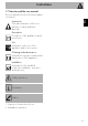
Instructions 1.7 How to read the user manual This user manual uses the following reading conventions: EN Instructions General information on this user manual, on safety and final disposal. Description Description of the appliance and its accessories. Use Information on the use of the appliance and its accessories. Cleaning and maintenance Information for proper cleaning and maintenance of the appliance. Installation Information for the qualified technician: Installation, operation and inspection.
Description 2 Description 2.
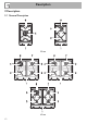
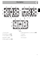
EN Description 90 cm 1 Control panel 2 Auxiliary burner (AUX) 3 Semi-rapid burner (SR) 4 Rapid burner (R) 5 Ultra-rapid burner (UR3) 6 Ultra-rapid double crown burner (UR2) 7 Left grid 8 Right grid 9 Central grid 41
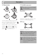
Description 2.2 Burner knobs 2.3 Available accessories Not all accessories are available on some models. Ring reducer Used for lighting and adjusting the hob burners. Press and turn anti-clockwise to in order to light the relative burners. Turn the knobs to the zone between the maximum and minimum setting to adjust the flame. Return the knobs to the position to turn off the burners. Useful when using small cookware. To be used only on AUX (auxiliary) burner. WOK ring Useful when using a wok.
Use 3 Use Improper use Danger of burns • Make sure that the flame-spreader crowns are correctly positioned in their seats with their respective burner caps. • Oils and fats could catch fire if overheated. Be very careful. • Do not leave the appliance unattended during cooking operations where fats or oils could be released. • Do not spray any spray product near the appliance. • Do not touch the appliance’s heating elements when it is running. Leave them to cool before cleaning.
Use 3.3 Using the accessories Ring reducers The ring reducers have to be placed on the hob grids. Make sure they are placed properly. Wait a few moments and repeat the operation. Keep the knob pressed in longer. In case of an accidental switching off, a safety device will be tripped, cutting off the gas supply, even if the gas cock is open. Return the knob to and wait at least 60 seconds before lighting it again. Correct positioning of the flamespreader crowns and burner caps 3.
Use For better burner efficiency and to minimise gas consumption, use pans with lids and of suitable size for the burner, so that the flames do not reach up the sides of the pan. Once the contents come to the boil, turn down the flame far enough to ensure that the liquid does not boil over. Cookware diameters: • Aux.: 12 - 14 cm. • Semi rapid: 16 - 20 cm. • Rapid: 22 - 26 cm. • Ultra-rapid: 22 - 26 cm.
Use A few precautions are necessary if you wish to use a griddle: • Griddles should be placed inside the perimeter of the hob and should not overlap this.
4 Cleaning and maintenance 4.2 Cleaning the appliance 4.1 Instructions To keep the surfaces in good condition, they should be cleaned regularly after use. Let them cool first. Improper use Risk of damage to surfaces • Do not use steam jets to clean the appliance. • Do not use cleaning products containing chlorine, ammonia or bleach on parts made of steel or that have metallic surface finishes (e.g. anodizing, nickelor chromium-plating).
Cleaning and maintenance Cooking hob grids Igniters and thermocouples Remove the grids and clean them in lukewarm water and non-abrasive detergent. Make sure to remove any encrustations. Dry them thoroughly and return them to the hob. For correct operation the igniters and thermocouples must always be perfectly clean. Check them frequently and clean them with a damp cloth if necessary. Remove any dry residues with a wooden toothpick or a needle.
Installation 5.2 Section cut from the countertop The following operation requires building and/or carpentry work and must therefore be carried out by a competent tradesman. Installation can be carried out on various materials such as masonry, metal, solid wood or plastic laminated wood as long as they are heat resistant (>90°C). 5.1 Safety instructions Heat production during appliance operation Risk of fire • Make sure that the cabinet material is heat resistant.
Installation 5.3 Mounting Over empty kitchen unit or drawers Over built-in oven unit If there are other pieces of furniture (lateral walls, drawers, etc.), dishwashers or fridges under the hob, a double-layer wooden base must be installed at least 10 mm from the bottom of the hob to avoid any accidental contact. It must only be possible to remove the double-layer base using suitable equipment.
Hob seal To prevent leakage of liquid between the frame of the hob and the work surface, place the insulating seal provided in position before assembly, as shown in the figure below. 2. Use light pressure to make the seal stick to the edge around the hole cut in the worktop. 3. Carefully trim the surplus away from edge (C) beyond the seal. 1. Refer to the dimensions in the figure, bearing in mind that all the sides "A" of the seal must brush against the hole. 5.
Installation 5.5 Gas connection Gas leak Danger of explosion Do not fix the hob using silicone. This would make it impossible to remove the hob, if necessary, without damaging it. 52 • After carrying out any operation, check that the tightening torque of gas connections is between 10 Nm and 15 Nm. • If required, use a pressure regulator that complies with current regulations. • At the end of the installation, check for any leaks with a soapy solution, never with a flame.
Connection with a steel hose Connection to LPG Make the connection to the gas mains using a continuous wall steel hose whose specifications comply with the applicable standard. Carefully screw the connector 3 to the gas connector 1 of the appliance, placing the seal 2 between them. Use a pressure regulator and make the connection on the gas cylinder following the guidelines set out in the standards in force.
Installation Extraction of the combustion products The combustion products may be extracted by means of hoods connected to a natural draught chimney whose efficiency is certain or via forced extraction. An efficient extraction system requires precision planning by a specialist qualified in this area and must comply with the positions and clearances indicated by the applicable standards. When the job is complete, the installer must issue a certificate of conformity. 5.
Installation 6. Remove the top. EN 3. Remove the flame-spreader crowns and relative burner caps. 4. Unscrew the screws under each burner to remove the fixing plate. Replacing the nozzles/air regulation 1. Unscrew screw "A" and push air regulator "B" as far as it will go. 5. Remove the gasket on each burner's thermocouple and igniter. 2.
Installation Adjusting the minimum setting for natural or town gas 3. Reposition support "B" so that nozzle "C" is covered completely. 4. Move the Venturi tube "D" to adjust the air flow until distance "X" is reached as indicated in the paragraph (see Table "Burner and nozzle characteristics" "Primary air adjustment (mm)") and then secure the tube by means of screw "A". 5. After adjusting each burner, reassemble the appliance correctly. The nozzle tightening torque must be no more than 3 Nm.
Installation Adjusting the minimum setting for LPG EN Tighten the screw located at the side of the cock rod clockwise all the way. Following adjustment to a gas other than the one originally set in the factory, replace the gas setting label on the appliance with the one corresponding to the new gas. The label is inserted inside the nozzle pack (where present). Lubricating the gas cocks Over time the gas cocks may become difficult to turn and get blocked.
Installation Gas types and Countries Gas types 1 Natural gas G20 G20 20 mbar G20/25 20/25 mbar 2 Natural gas G20 G20 25 mbar 3 Natural gas G25.1 G25.1 25 mbar 4 Natural gas G25 G25 20 mbar 5 Natural gas G27 G27 20 mbar 6 Natural gas G2.350 G2.
Installation 1 Natural gas G20 - 20 mbar Rated heating capacity (kW) Nozzle diameter (1/100 mm) Reduced flow rate (W) Primary air (mm) 2 Natural gas G20 - 25 mbar Rated heating capacity (kW) Nozzle diameter (1/100 mm) Reduced flow rate (W) Primary air (mm) 3 Natural gas G25.
Installation 8 LPG G30/G31 - 37 mbar Rated heating capacity (kW) Nozzle diameter (1/100 mm) Reduced flow rate (W) Primary air (mm) Rated flow rate G30 (g/h) Rated flow rate G31 (g/h) 9 LPG G30/G31 - 50 mbar Rated heating capacity (kW) Nozzle diameter (1/100 mm) Reduced flow rate (W) Primary air (mm) Rated flow rate G30 (g/h) Rated flow rate G31 (g/h) 10 Town gas G110 – 8 mbar Rated heating capacity (kW) Nozzle diameter (1/100 mm) Reduced flow rate (W) Primary air (mm) AUX SR R UR2 (int + ext) UR3 1.
Installation Power voltage Danger of electrocution • Have the electrical connection performed by authorised technicians. • Use personal protective equipment. • The appliance must be connected to ground in compliance with electrical system safety standards. • Disconnect the mains power supply. • Do not pull the cable to remove the plug. • Use cables withstanding a temperature of at least 90°C. • The tightening torque of the screws of the terminal board leads must be 1.5 - 2 Nm.
Installation 5.8 Instructions for the installer • The plug must be accessible after installation. Do not bend or trap the power cable. • The appliance must be installed according to the installation diagrams. • Do not try to unscrew or force the threaded elbow of the fitting. You may damage this part of the appliance, which may void the manufacturer’s warranty. • Use soap and water to check for gas leaks on all connections. DO NOT use naked flames to find leaks.