Contents 1.1 1.2 1.3 1.4 1.5 1.6 1.7 General safety instructions Manufacturer liability Appliance purpose Identification plate This user manual Disposal How to read the user manual 2 Description 2.1 General Description 2.2 Symbols 2.3 Available accessories 3 Use 3.1 3.2 3.3 3.4 34 34 37 37 37 37 38 39 40 40 41 42 43 Instructions First use Using the accessories Using the hob 43 43 43 44 4 Cleaning and maintenance 47 4.1 Instructions 4.2 Cleaning the appliance 47 47 5 Installation 5.1 5.2 5.3 5.
Instructions 1 Instructions 1.1 General safety instructions Risk of personal injury • During use the appliance and its accessible parts become very hot. Never touch the heating elements during use. • Never try to put out a fire or flames with water: turn off the appliance and smother the flames with a fire blanket or other appropriate cover.
• Do not use aerosols in the vicinity of this appliance whilst it is in use. • Switch off the appliance after use. • Do not modify this appliance. • Do not try to repair the appliance yourself or without the intervention of a qualified technician. • Do not pull the cable to remove the plug. • If the power supply cable is damaged, contact technical support immediately and they will replace it. Risk of damaging the appliance • Do not sit on the appliance. • Do not use steam jets to clean the appliance.
Instructions • Do not wash the removable components such as the hob grids, flame-spreader crowns and burner caps in a dishwasher. Installation • This appliance must not be installed in a boat or caravan. • This appliance must not be installed on a pedestal. • Position the appliance into the cabinet cut-out with the help of a second person. • To prevent any possible overheating, the appliance should not be installed behind a decoration door or a panel.
For this appliance • Do not obstruct ventilation openings and heat dispersal slots. • Do not insert pointed metal objects (cutlery or utensils) into the slots in the appliance. • Do not use the appliance to heat rooms for any reason. • The appliance is not designed to operate with external timers or with remote-control systems. 1.
Instructions 1.6 Disposal This appliance must be disposed of separately from other waste (Directives 2002/95/EC, 2002/96/EC, 2003/108/EC). The appliance does not contain substances in quantities sufficient to be considered hazardous to health and the environment, in accordance with current European directives. To dispose of the appliance: • In order to prevent children from becoming trapped inside, remove the doors (if present) and leave the accessories (racks and trays) in the positions of use.
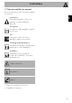
Instructions 1.7 How to read the user manual This user manual uses the following reading conventions: EN Instructions General information on this user manual, on safety and final disposal. Description Description of the appliance and its accessories. Use Information on the use of the appliance and its accessories. Cleaning and maintenance Information for proper cleaning and maintenance of the appliance. Installation Information for the qualified technician: Installation, operation and inspection.
Description 2 Description 2.
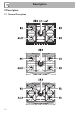
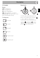
Description 2.2 Symbols Burner knobs AUX: Auxiliary burner. SR: Semi-rapid burner. RR: Reduced rapid burner. UR3: Ultra-rapid triple crown burner. UR2 int + ext: Ultra-rapid double crown burner (internal and external). Cooking zones EN Burners Used for lighting and adjusting the hob Front right burners. Press and turn anti-clockwise to in order to light the relative burners. Turn the knobs to the zone between the Front left maximum and minimum setting to adjust the flame.
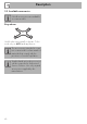
Description 2.3 Available accessories Not all accessories are available on some models. Ring reducer Useful when using small cookware. To be used only on AUX (auxiliary) burner. The accessories intended to come into contact with food are made of materials that comply with the provisions of current legislation. Supplied and optional accessories can be requested to Authorised Service Centres. Use only original accessories supplied by the manufacturer.
Use 3 Use 3.1 Instructions Improper use Danger of burns • Make sure that the flame-spreader crowns are correctly positioned in their seats with their respective burner caps. • Oils and fats could catch fire if overheated. Be very careful. • Do not leave the appliance unattended during cooking operations where fats or oils could be released. • Do not spray any spray product near the appliance. • Do not touch the appliance’s heating elements when it is running. Leave them to cool before cleaning.
Use 3.4 Using the hob All the appliance’s control and monitoring devices are located together on the front panel. The burner controlled by each knob is shown next to the knob. The appliance is equipped with an electronic ignition device. Simply press the knob and turn it counterclockwise to the maximum flame symbol, until the burner ignites. If the burner does not light in the first 15 seconds, turn the knob to and wait 60 seconds before trying again.
Use Cookware diameters: • AUX: 12 - 14 cm. • SR: 16 - 20 cm. • RR: 22 - 26 cm. • UR3: 22 - 26 cm. • UR2 int + ext: 22 - 26 cm. To prevent burns or damage to the hob or the counter top during cooking, all pans or griddles must be placed inside the perimeter of the hob.
Use A few precautions are necessary if you wish to use a griddle: • The griddles should not exceed the perimeter of the hob. • Aluminium griddles with Teflon anti-stick coating should be pre-heated for a maximum of 5 minutes in order to avoid damage to the appliance and the Teflon coating. After pre-heating, place the foodstuffs on the griddle to cook them; do not exceed 40 minutes of total use for the griddle.
4 Cleaning and maintenance 4.2 Cleaning the appliance 4.1 Instructions To keep the surfaces in good condition, they should be cleaned regularly after use. Let them cool first. Improper use Risk of damage to surfaces • Do not use steam jets to clean the appliance. • Do not use cleaning products containing chlorine, ammonia or bleach on parts made of steel or that have metallic surface finishes (e.g. anodizing, nickelor chromium-plating).
Cleaning and maintenance Cooking hob grids Igniters and thermocouples Remove the grids and clean them in lukewarm water and non-abrasive detergent. Make sure to remove any encrustations. Dry them thoroughly and return them to the hob. For correct operation the igniters and thermocouples must always be perfectly clean. Check them frequently and clean them with a damp cloth if necessary. Remove any dry residues with a wooden toothpick or a needle.
Installation 5.2 Section cut from the countertop The following operation requires building and/or carpentry work and must therefore be carried out by a competent tradesman. Installation can be carried out on various materials such as masonry, metal, solid wood or plastic laminated wood as long as they are heat resistant (>90°C). 5.1 Safety instructions Heat production during appliance operation Risk of fire • Make sure that the cabinet material is heat resistant.
Installation Overall dimensions: gas and electrical connection location (measures in mm) 5.3 Mounting Over built-in oven unit The clearance between the hob and the kitchen furniture or other installed appliances must be enough to ensure sufficient ventilation and air discharge. If installed above an oven, a space must be left between the bottom of the hob and the top of the appliance installed below.
Installation Over empty kitchen unit or drawers EN If there are other pieces of furniture (lateral walls, drawers, etc.), dishwashers or fridges under the hob, a double-layer wooden base must be installed at least 10 mm from the bottom of the hob to avoid any accidental contact. It must only be possible to remove the double-layer base using suitable equipment. opens on rear Failure to install the double-layer wooden base exposes the user to possible accidental contact with sharp or hot parts.
Installation 2. Use light pressure to make the seal stick to the edge around the hole cut in the worktop. 3. Carefully trim the surplus away from edge (C) beyond the seal. 5.4 Fixing to the supporting structure Secure the hob to the piece of furniture through the appropriate bracket (A). 5.5 Gas connection Gas leak Danger of explosion • After carrying out any operation, check that the tightening torque of gas connections is between 10 Nm and 15 Nm.
Installation Make the connection to the gas mains using a continuous wall steel hose whose specifications comply with the applicable standard. Carefully screw the connector 3 to the gas connector 1 of the appliance, placing the seal 2 between them. Connection with a steel hose with conical fitting Make the connection to the gas mains using a continuous wall steel hose whose specifications comply with the applicable standard.
Installation Room ventilation The appliance should be installed in rooms that have a permanent air supply in accordance with the standards in force. The room where the appliance is installed must have enough air flow for the regular combustion of gas and the necessary air change in the room itself. The air vents, protected by grilles, must be the right size to comply with current regulations and positioned so that no part of them is obstructed, not even partially.
Installation 5.6 Adaptation to different types of gas 3. Remove the flame-spreader crowns and relative burner caps. EN If other types of gas are to be used, the nozzles must be replaced and the primary air must be adjusted. In order to replace the nozzles and adjust the burners, the hob top must be removed. Removing the hob top 1. Remove the grids from the hob. 4. Unscrew the screws under each burner to remove the fixing plate. 2. Remove the knobs lifting them from their housing. 5.
Installation 6. Remove the top. 3. Reposition support "B" so that nozzle "C" is covered completely. Replacing the nozzles/air regulation 1. Unscrew screw "A" and push air regulator "B" as far as it will go. 4. Move the Venturi tube "D" to adjust the air flow until distance "X" is reached as indicated in the paragraph (see Table "Burner and nozzle characteristics" "Primary air adjustment (mm)") and then secure the tube by means of screw "A". 5.
Installation Light the burner and turn it to the minimum position. Remove the gas tap knob and turn the adjustment screw next to the tap rod (depending on the model) until the correct minimum flame is obtained. Refit the knob and verify that the burner flame is stable. Turn the knob rapidly from the maximum to the minimum setting: The flame should not go out. Repeat the operation on all gas cocks.
Installation Gas types and Countries Gas types 1 Natural gas G20 G20 20 mbar G20/25 20/25 mbar 2 Natural gas G20 G20 25 mbar 3 Natural gas G25 G25 25 mbar G25.3 25 mbar 4 Natural gas G25.1 G25.1 25 mbar 5 Natural gas G25 G25 20 mbar 6 Natural gas G27 G27 20 mbar 7 Natural gas G2.350 G2.
Installation Burner and nozzle specifications tables AUX SR RR UR2(int +ext) UR3 1.10 73 400 1.5 AUX 1.70 92 450 1.5 SR 2.60 115 650 1 RR 1.10 + 3.90 3.90 73 + 140 140 400 + 1200 1400 2+3 2 UR2(int + ext) UR3 1.10 73 400 1.5 AUX 1.70 87 450 1 SR 2.60 110 650 1 RR 1.10 + 3.90 3.9 73 + 132 132 400 + 1200 1400 3+4 1.5 UR2(int + ext) UR3 1.10 76 400 1 AUX 1.70 98 450 1 SR 2.70 123 650 1 RR 1.0 + 4.0 3.90 76 + 150 145 400 + 1200 1400 1.5 + 2 1.5 UR2(int + ext) UR3 1.10 76 400 1.5 AUX 1.
Installation 8 LPG G30/31 - 30/37 mbar Rated heating capacity (kW) Nozzle diameter (1/100 mm) Reduced flow rate (W) Primary air (mm) Rated flow rate G30 (g/h) Rated flow rate G31 (g/h) 9 LPG G30/31 - 37 mbar Rated heating capacity (kW) Nozzle diameter (1/100 mm) Reduced flow rate (W) Primary air (mm) Rated flow rate G30 (g/h) Rated flow rate G31 (g/h) 10 LPG G30/31 - 50 mbar Rated heating capacity (kW) Nozzle diameter (1/100 mm) Reduced flow rate (W) Primary air (mm) Rated flow rate G30 (g/h) Rated flow rat
Installation Power voltage Danger of electrocution • Have the electrical connection performed by authorised technicians. • Use personal protective equipment. • The appliance must be connected to ground in compliance with electrical system safety standards. • Disconnect the mains power supply. • Do not pull the cable to remove the plug. • Use cables withstanding a temperature of at least 90°C. • The tightening torque of the screws of the terminal board leads must be 1.5 - 2 Nm.
Installation Testing 5.8 Instructions for the installer At the end of installation, carry out a brief inspection test. If the hob fails to operate, after checking that you have carried out the instructions correctly, unplug the appliance and contact Technical Support. • The plug must be accessible after installation. Do not bend or trap the power cable. • The appliance must be installed according to the installation diagrams. • Do not try to unscrew or force the threaded elbow of the fitting.