Contents 1.1 1.2 1.3 1.4 1.5 1.6 1.7 1.8 1.9 4 General safety instructions Manufacturer liability Appliance purpose Identification plate This user manual Disposal How to read the user manual To save energy Information for European Control Bodies 2 Description 2.1 2.2 2.3 2.4 2.5 General Description Cooking hob Control panel Other parts Available accessories Cleaning the hob Cleaning the door Cleaning the oven cavity Vapor Clean Extraordinary maintenance 5 Installation 5.1 5.2 5.3 5.4 5.
Instructions 1 Instructions 1.1 General safety instructions Risk of personal injury • During use the appliance and its accessible parts become very hot. Keep children well away from the appliance. • Protect your hands by wearing oven gloves when moving food inside the oven. • Never try to put out a fire or flames with water: turn off the appliance and smother the flames with a fire blanket or other appropriate cover.
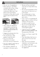
• Keep the oven door closed during cooking. • If you need to move food or at the end of cooking, open the door 5 cm for a few seconds, let the steam come out, then open it fully. • Do not open the storage compartment (where present) when the oven is on and still hot. • The items inside the storage compartment could be very hot after using the oven. • Switch off the appliance after use. • Do not pull the cable to remove the plug.
Instructions • Do not sit on the appliance. • Racks and trays should be inserted as far as they will go into the side guides. The mechanical safety locks that prevent them from being removed must face downwards and towards the back of the oven. • Never leave the appliance unattended during cooking operations where fats or oils could overheat and take fire. Be very careful • Danger of fire: do not store items on the cooking surfaces. • Do not spray any spray products near the oven.
• Do not put empty pans or frying pans on switched on cooking zones. • Do not use rough or abrasive materials or sharp metal scrapers. • Do not use cleaning products containing chlorine, ammonia or bleach on parts made of steel or that have metallic surface finishes (e.g. anodizing, nickel- or chromium-plating). • Do not wash the removable components such as the hob grids, flame-spreader crowns and burner caps in a dishwasher. • Never use the oven door to lever the appliance into place when fitting.
Instructions • The adjustment conditions for this appliance are shown on the gas setting label. • Have the gas connection performed by authorised staff. • Installation using a hose must be carried out so that the length of the hose does not exceed 2 metres when fully extended for steel hoses and 1.5 metres for rubber hoses. • The hoses should not come into contact with moving parts and should not be crushed in any way. • If required, use a pressure regulator that complies with current regulations.
• use of non-original spare parts. 1.3 Appliance purpose • This appliance is intended for cooking food in the home environment. Every other use is considered inappropriate. • The appliance is not designed to operate with external timers or with remote-control systems. 1.4 Identification plate The identification plate bears the technical data, serial number and brand name of the appliance. Do not remove the identification plate for any reason. 1.
Instructions • Deliver the appliance to the appropriate recycling centre for electrical and electronic equipment waste, or return it to the retailer when purchasing an equivalent product, on a one for one basis. Our appliances are packaged in non-polluting and recyclable materials. • Deliver the packing materials to the appropriate recycling centre. Plastic packaging Danger of suffocation • Do not leave the packaging or any part of it unattended. • Do not let children play with the plastic bags. 1.
1.8 To save energy • Only preheat the appliance if the recipe requires you to do so. • Unless otherwise indicated on the package, defrost frozen foods before placing them in the oven. • When cooking several types of food it is recommended to cook the foods one after the other to make the best use of the already hot oven. • Use dark metal moulds: They help to absorb the heat better. • Remove all trays and racks which are not required during cooking. • Stop cooking a few minutes before the time normally used.
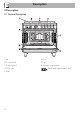
Description 2 Description 2.
Description AUX = Auxiliary SR = Semi-rapid EN 2.2 Cooking hob R = Rapid UR = Ultra rapid 2.3 Control panel 1 Programmer clock 4 Function knob For displaying the current time, setting programmed cooking operations and the minute minder timer. The oven’s various functions are suitable for different cooking modes. After selecting the required function, set the cooking temperature using the temperature knob. 2 Temperature knob This knob allows you to select the cooking temperature.
Description 2.4 Other parts 2.5 Available accessories Shelves Tray The appliance features shelves to position trays and racks at different heights. The insertion heights are indicated from the bottom upwards (see 2.1 General Description). Interior lighting The appliance interior lighting comes on: • When the door is opened • When any function is selected, apart from the function. Useful for collecting fat from foods placed on the rack above.
Description EN Tray rack To be placed over the top of the oven tray; for cooking foods which may drip. Ring reducers Useful when using small cookware. WOK ring Useful when using a wok. The accessories intended to come into contact with food are made of materials that comply with the provisions of current legislation. Supplied and optional accessories can be requested to Authorised Assistance Centres. Use only original accessories supplied by the manufacturer.
Use 3 Use Instructions High temperature inside the oven during use Danger of burns • Keep the oven door closed during cooking. • Protect your hands wearing heat resistant gloves when moving food inside the oven. • Do not touch the heating elements inside the oven. • Do not pour water directly onto very hot trays. • Keep children under the age of 8 away from the appliance when it is in use.
High temperature inside the oven during use Danger of fire or explosion • Do not spray any spray products near the oven. • Do not use or leave flammable materials near the oven or the storage compartment. • Do not use plastic cookware or containers when cooking food. • Do not put sealed tins or containers in the oven. • Do not leave the oven unattended during cooking operations where fats or oils could be released. • Remove all trays and racks which are not required during cooking.
Use 3.1 Using the accessories Racks and trays Ring reducers Racks and trays have to be inserted into the side guides until they come to a complete stop. The mechanical safety locks that prevent the rack from being taken out accidentally have to face downwards and towards the oven back. The ring reducers have to be placed on the hob grids. Make sure they are placed properly. Gently insert racks and trays into the oven until they come to a stop.
The burner may go out when the knob is released: In this case, the thermocouple has not heated up sufficiently. Wait a few moments and repeat the operation. Keep the knob pressed in longer. In case of an accidental switching off, a safety device will be tripped, cutting off the gas supply, even if the gas cock is open. Return the knob to and wait at least 60 seconds before lighting it again.
Use 3.4 Using the oven Switching on the oven To switch on the oven: 1. Select the cooking function using the function knob. 2. Select the temperature using the temperature knob. Ensure that the programmer clock shows the cooking duration symbol , otherwise it will not be possible to turn on the oven. Press the keys and at the same time to reset the programmer clock. Functions list Static As the heat comes from above and below at the same time, this system is particularly suitable for certain types of food.
Fan with grill The air produced by the fan softens the strong heatwave generated by the grill, grilling perfectly even very thick foods. Perfect for large cuts of meat (e.g. shin of pork). Fan assisted The operation of the fan, combined with traditional cooking, ensures consistent cooking even with complex recipes. Perfect for biscuits and cakes, even when simultaneously cooked on several levels. (For multiple-level cooking, we recommend using the 2nd and 4th shelves.
Use 3.5 Cooking advice General advice • Use a fan assisted function to achieve consistent cooking at several levels. • It is not possible to shorten cooking times by increasing the temperature (the food could be overcooked on the outside and undercooked on the inside). Advice for cooking meat • Cooking times vary according to the thickness and quality of the food and to consumer taste. • Use a meat thermometer when roasting meat, or simply press on the roast with a spoon.
Use Setting the time EN 3.6 Digital programmer If the time is not set, the oven will not switch on. On the first use, or after a power failure, the digits will be flashing on the appliance’s display. 1. Press the keys and at the same time. The dot between the hours and the minutes flashes.
Use Timed cooking Timed cooking is the function which allows a cooking operation to be started and then ended after a specific length of time set by the user. 1. After selecting a cooking function and temperature, press the key . The display will show the digits and the symbol displayed between the hours and the minutes. 2. Use the key or to set the required minutes. 3. Wait approx. 5 seconds without pressing any key in order for the function to activate.
3. Use the key or to set the required minutes. 4. Wait approx. 5 seconds without pressing any key in order for the function to activate. The current time and the Minute minder timer symbols and will appear on the display. 5. At the end of cooking the heating elements will be deactivated. On the The minute minder timer can be activated at any time. display, the symbol turns off, the symbol flashes and the buzzer sounds. 6. To turn off the buzzer just press any key of the programmer clock. 7.
Use Cooking information table Lasagne Pasta bake 3-4 3-4 Static Static Runner position from the bottom 1 1 Roast veal Pork loin Sausages Roast beef Roast rabbit Turkey breast Roast pork neck Roast chicken 2 2 1.5 1 1.5 3 2-3 1.
4 Cleaning and maintenance Instructions Improper use Risk of damage to surfaces • Do not use steam jets to clean the appliance. • Do not use cleaning products containing chlorine, ammonia or bleach on parts made of steel or that have metallic surface finishes (e.g. anodizing, nickelor chromium-plating). • Do not use abrasive or corrosive detergents (e.g. scouring powders, stain removers and metallic sponges) on glass parts. • Do not use rough or abrasive materials or sharp metal scrapers.
Cleaning and maintenance 4.1 Cleaning the hob Igniters and thermocouples Cooking hob grids For correct operation the igniters and thermocouples must always be perfectly clean. Check them frequently and clean them with a damp cloth if necessary. Remove any dry residues with a wooden toothpick or a needle. Remove the grids and clean them in lukewarm water and non-abrasive detergent. Make sure to remove any encrustations. Dry them thoroughly and return them to the hob.
4.2 Cleaning the door Removing the door For easier cleaning, the door can be removed and placed on a canvas. To remove the door proceed as follows: 1. Open the door completely and insert two pins into the holes on the hinges indicated in the figure. 3. To reassemble the door, put the hinges in the relevant slots in the oven, making sure that grooved sections A are resting completely in the slots. Lower the door and once it is in place remove the pins from the holes in the hinges.
Cleaning and maintenance Removing the internal glass panes For easier cleaning the internal glass panes of the door can be removed. 1. Open the door. 2. Position the retaining clips in the holes in the hinges in order to prevent accidental closing of the door. 3. Pull the rear part of the internal glass pane gently upwards, following the movement indicated by the arrows (1). 5. Remove the intermediate glass pane by lifting it upwards. 6. Clean the external glass pane and the panes removed previously.
4.3 Cleaning the oven cavity In order to keep your oven in the best possible condition, clean it regularly after letting it cool down. Avoid letting food residue dry inside the oven cavity, as this could damage the enamel. Take out all removable parts before cleaning. For easier cleaning, we recommend removing: • The door • The rack/tray support frames • The seal.
Cleaning and maintenance • Pour approximately 40 cc of water into the tray. Make sure it does not overflow out of the cavity. Vapor Clean setting 1. Turn the function knob to the symbol the temperature knob to the symbol and . 2. Set a cooking time of 18 minutes using the programmer clock. The Vapor Clean cycle starts a few seconds after the last press on the programmer clock keys. 3.
Cleaning and maintenance Installing and removing the seal To remove the seal: • Unhook the clips in the 4 corners and in the centre, then pull the seal. Replacing the internal light bulb EN 4.5 Extraordinary maintenance Live parts Danger of electrocution • Unplug the appliance. The oven is fitted with a 40W light bulb. 1. Completely remove all accessories from inside the oven. 2. Remove the rack/tray support frames. 3. Remove the bulb cover using a tool (e.g. a screwdriver).
Cleaning and maintenance 4. Slide out and remove the light bulb. Do not touch the halogen lamp directly with your fingers, but wrap it in an insulating material. 5. Fit the new light bulb. 6. Refit the cover. Ensure the moulded part of the glass (A) is facing the door. 7. Press the cover completely down so that it attaches perfectly to the bulb support.
5 Installation 5.1 Gas connection Gas leak Danger of explosion • After carrying out any operation, check that the tightening torque of gas connections is between 10 Nm and 15 Nm. • If required, use a pressure regulator that complies with current regulations. • At the end of the installation, check for any leaks with a soapy solution, never with a flame. • Installation using a hose must be carried out so that the length of the hose does not exceed 2 metres when fully extended for steel hoses and 1.
Installation After having tightened the hose connector(s), push the gas hose 6 onto the hose connector and secure it with the clamp 5 that is compliant with the standard in force. Connection with a steel hose with bayonet fitting Carry out the connection to the gas mains using a steel hose with bayonet fitting compliant with B.S. 669. Apply insulating material to the thread of the gas hose connector 4 and then tighten the adapter 3.
Connection with a steel hose with conical fitting Make the connection to the gas mains using a continuous wall steel hose whose specifications comply with the applicable standard. Carefully screw the hose connector 3 to the appliance’s gas connector 1 (½” thread ISO 228-1), placing the supplied seal 2 between them. Apply insulating material to the thread of connector 3, then tighten the steel hose 4 to the connector 3.
Installation When the job is complete, the installer must issue a certificate of conformity. Replacing nozzles 1 Extraction using a hood 2 Extraction without a hood A Single natural draught chimney B Single chimney with extractor fan C Directly outdoors with wall- or windowmounted extractor fan D Directly outdoors through wall Air 2. Replace the nozzles using a 7 mm socket wrench according to the gas to be used (see "Nozzle and burner specification tables"). 1.
Installation EN Refit the knob and verify that the burner flame is stable. Turn the knob rapidly from the maximum to the minimum setting: The flame should not go out. Repeat the operation on all gas cocks. Adjusting the minimum setting for LPG Tighten the screw located at the side of the cock rod clockwise all the way. Following adjustment to a gas other than the one originally set in the factory, replace the gas setting label on the appliance with the one corresponding to the new gas.
Installation Burner and nozzle characteristics tables Natural Gas G20 - 20 mbar Rated heating capacity (kW) Nozzle diameter (1/100 mm) Pre-chamber (printed on nozzle) Reduced flow rate (W) Natural gas G25 - 20 mbar Rated heating capacity (kW) Nozzle diameter (1/100 mm) Pre-chamber (printed on nozzle) Reduced flow rate (W) LPG G30/G31 - 50 mbar Rated heating capacity (kW) Nozzle diameter (1/100 mm) Pre-chamber (printed on nozzle) Reduced flow rate (W) Rated flow rate G30 (g/h) Rated flow rate G31 (g/h) AUX
Installation X 150 mm Y 750 mm EN Any wall units installed above the appliance’s worktop must be positioned at least Y mm from it. If a hood is installed above the hob, refer to the hood instruction manual to ensure the correct clearance is left.
Installation Appliance overall dimensions A 900 mm B 600 mm C1 D min. 150 mm 900 - 915 mm H 750 mm I 450 mm L2 900 mm 1 Minimum distance from side walls or other flammable material. 2 Minimum cabinet width (=A). Dimensions of the appliance: locations of gas and electric connections (mm) A 124 B 38 C 42 D 634 F min. 105 - max.
Installation Heavy appliance Risk of damage to the appliance • Insert the front feet first and then the rear ones. Fastening to the wall EN Positioning and levelling The anti-tip devices must be installed in order to prevent the appliance tipping over. 1. Screw the wall fastening plate to the rear of the appliance. • After making the gas and electrical connections, screw on the four feet supplied with the appliance. The appliance must sit level on the floor to ensure stability.
Installation 3. Assemble the fastening bracket. 4. Align the base of the hook on the fastening bracket with the base of the slot on the wall fastening plate. 44 5. Align the base of the fastening bracket with the ground and tighten the screws to fix the measurements. 6. Use 50 mm for the distance from the side of the appliance to the bracket holes.
7. Move the bracket onto the wall and mark the position of the holes to be drilled in the wall. Assembling the upstand The upstand provided is an integral part of the product. It must be fastened to the appliance prior to installation. The upstand must always be positioned and secured correctly on the appliance. 1. Unscrew the 2 nuts B on the back of the worktop. 2. Position the upstand above the worktop, taking care to align the pins C with the holes D. 3.
Installation 5.4 Electrical connection Power voltage Danger of electrocution • Have the electrical connection performed by authorised technical personnel. • Use personal protective equipment. • The appliance must be connected to earth in compliance with electrical system safety standards. • Disconnect the mains supply. • Do not pull the cable to remove the plug. • Use cables withstanding a temperature of at least 90 °C. • The tightening torque of the screws of the terminal board conductors must be 1.
Installation EN 5.5 Instructions for the installer • The plug must be accessible after installation. Do not bend or trap the power cable. • The appliance must be installed according to the installation diagrams. • Do not try to unscrew or force the threaded elbow of the fitting. You may damage this part of the appliance, which may void the manufacturer’s warranty. • Use soap and water to check for gas leaks on all connections. DO NOT use naked flames when looking for leaks.