Contents 1.1 1.2 1.3 1.4 1.5 1.6 1.7 1.8 4 General safety instructions Manufacturer liability Appliance purpose Identification plate This user manual Disposal How to read the user manual To save energy 2 Description 2.1 2.2 2.3 2.4 2.
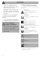
Instructions 1 Instructions 1.1 General safety instructions Risk of personal injury • During use the appliance and its accessible parts become very hot. Keep children well away from the appliance. • Protect your hands by wearing oven gloves when moving food inside the oven. • Never try to put out a fire or flames with water: turn off the appliance and smother the flames with a fire blanket or other appropriate cover.
• Keep the oven door closed during cooking. • If you need to move food or at the end of cooking, open the door 5 cm for a few seconds, let the steam come out, then open it fully. • Do not open the storage compartment (where present) when the oven is on and still hot. • The items inside the storage compartment could be very hot after using the oven. • Switch off the appliance after use. • Do not pull the cable to remove the plug.
Instructions • Do not sit on the appliance. • Racks and trays should be inserted as far as they will go into the side guides. The mechanical safety locks that prevent them from being removed must face downwards and towards the back of the oven. • Never leave the appliance unattended during cooking operations where fats or oils could overheat and take fire. Be very careful • Danger of fire: do not store items on the cooking surfaces. • Do not spray any spray products near the oven.
• Do not put empty pans or frying pans on switched on cooking zones. • Do not use rough or abrasive materials or sharp metal scrapers. • Do not use cleaning products containing chlorine, ammonia or bleach on parts made of steel or that have metallic surface finishes (e.g. anodizing, nickel- or chromium-plating). • Do not wash the removable components such as the hob grids, flame-spreader crowns and burner caps in a dishwasher. • Never use the oven door to lever the appliance into place when fitting.
Instructions • The adjustment conditions for this appliance are shown on the gas setting label. • Have the gas connection performed by authorised staff. • Installation using a hose must be carried out so that the length of the hose does not exceed 2 metres when fully extended for steel hoses and 1.5 metres for rubber hoses. • The hoses should not come into contact with moving parts and should not be crushed in any way. • If required, use a pressure regulator that complies with current regulations.
• use of non-original spare parts. 1.3 Appliance purpose • This appliance is intended for cooking food in the home environment. Every other use is considered inappropriate. • The appliance is not designed to operate with external timers or with remote-control systems. 1.4 Identification plate The identification plate bears the technical data, serial number and brand name of the appliance. Do not remove the identification plate for any reason. 1.
Instructions • Deliver the appliance to the appropriate recycling centre for electrical and electronic equipment waste, or return it to the retailer when purchasing an equivalent product, on a one for one basis. Our appliances are packaged in non-polluting and recyclable materials. • Deliver the packing materials to the appropriate recycling centre. Plastic packaging Danger of suffocation • Do not leave the packaging or any part of it unattended. • Do not let children play with the plastic bags. 1.
Instructions EN 1.8 To save energy • Only preheat the appliance if the recipe requires you to do so. • Unless otherwise indicated on the package, defrost frozen foods before placing them in the oven. • When cooking several types of food it is recommended to cook the foods one after the other to make the best use of the already hot oven. • Use dark metal moulds: They help to absorb the heat better. • Remove all trays and racks which are not required during cooking.
Description 2 Description 2.
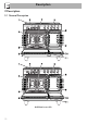
EN Description Pyrolytic models 1 Upstand 2 Cooking hob 3 Control panel 4 Main oven light 5 Main oven seal 6 Main oven door 7 Main oven fan 8 Auxiliary oven light 9 Auxiliary oven seal 10 Auxiliary oven door 11 Storage compartment Rack/tray support frames 13
Description 2.2 Cooking hob AUX = Auxiliary burner SR = Semi-rapid burner R = Rapid UR-3c = Ultra-rapid burner 2.
1 Programmer clock 7 Auxiliary oven indicator light Useful for displaying the current time, setting programmed cooking operations and programming the minute minder timer. The indicator light comes on to indicate that the oven is heating up. It turns off as soon as it reaches the set temperature. It flashes regularly to indicate that the temperature set inside the oven is kept constant. 2 Main oven temperature knob This knob allows you to select the cooking temperature.
Description The fan cools the appliance and comes into operation during cooking. The fan causes a steady outflow of air that exits from the rear of the appliance and which may continue for a brief period of time even after the appliance has been turned off. Do not obstruct ventilation openings and heat dispersal slots. Interior lighting The appliance’s interior lighting comes on: (main oven) • when the door is opened; • when any function is selected, apart from the function. 2.
Description Tray rack (on some models only) EN Tray (on some models only) Useful for collecting fat from foods placed on the rack above. Deep tray To be placed over the top of the tray; for cooking foods which may drip. Useful for collecting fat from foods placed on the rack above and for cooking pies, pizzas and baked desserts.
Description Rack Useful for supporting containers with food during cooking. Self-cleaning panels (on some models only) Useful for absorbing small grease residues.
Use High temperature inside the oven during use Danger of burns • Keep the oven door closed during cooking. • Protect your hands wearing heat resistant gloves when moving food inside the oven. • Do not touch the heating elements inside the oven. • Do not pour water directly on very hot trays. • Keep children under the age of 8 away from the oven when it is in use. • If you need to move food or at the end of cooking, open the door 5 cm for a few seconds, let the steam come out, then open it fully.
Use High temperature inside the storage compartment Danger of fire or explosion • Do not spray any spray product near the appliance. • Do not use or leave flammable materials near the appliance or the storage compartment. • Do not use plastic cookware or containers for cooking. • Do not place sealed tins or containers in the oven cavity. • Do not leave the appliance unattended during cooking operations where fats and oils could be released. • Remove all trays and racks which are not required during cooking.
3.1 To save energy 3.2 Using the accessories • Preheat the appliance only if the recipe requires it. • Unless differently stated on the package, defrost frozen food before placing it in the cooking compartment. • In case of multiple cooking, it is recommended to cook food one after the other to exploit the already hot cooking compartment. • Use dark metal moulds: They help to absorb the heat better. • Remove all trays and racks which are not required during cooking.
Use Racks and trays 3.3 Using the hob Racks and trays have to be inserted into the side guides until they come to a complete stop. • The mechanical safety locks that prevent the rack from being taken out accidentally have to face downwards and towards the oven back. All the appliance’s control and monitoring devices are located together on the front panel. The burner controlled by each knob is shown next to the knob. The appliance is equipped with an electronic ignition device.
Correct positioning of the flamespreader crowns and burner caps Before lighting the hob burners, make sure that the flame-spreader crowns are correctly positioned in their seats with their respective burner caps. Make sure that the holes 1 in the flame-spreader crowns are aligned with the igniters 3 and thermocouples 2.
Use 3.5 Using the ovens Switching on the main oven 1. Select the cooking function using the function knob. 2. Select the temperature using the temperature knob. Ensure that the programmer clock shows the cooking duration symbol , otherwise it will not be possible to turn on the oven. Press the keys and at the same time to reset the programmer clock. Fan + lower element The combination of the fan with just the lower heating element allows cooking to be completed more rapidly.
Fan assisted (on some models only) The operation of the fan, combined with traditional cooking, ensures consistent cooking even with complex recipes. Perfect for biscuits and cakes, even when simultaneously cooked on several levels. (For multiple-level cooking, we recommend using the 2nd and 4th runners). Eco This function is particularly suitable for cooking on a single shelf with low energy consumption.
Use Pyrolytic (on some models only) Setting this function, the oven reaches temperatures up to 500 °C, destroying all the grease which forms on the internal walls. Switching on the auxiliary oven Turn the temperature/function knob to the required temperature, from a minimum of 50 °C to a maximum of 245 °C, or to the required function (at the maximum temperature). Auxiliary oven functions Light bulb Turns on the light inside the oven cavity.
General advice • Use a fan assisted function to achieve consistent cooking at several levels. • It is not possible to shorten cooking times by increasing the temperature (the food could be overcooked on the outside and undercooked on the inside). • For the same total weight, cooking time will be greater for cooking a whole piece than when it is cut into smaller pieces. Advice for cooking meat • Cooking times vary according to the thickness and quality of the food and to consumer taste.
Use Advice for defrosting and proving • Place frozen foods without their packaging in a lidless container on the first shelf of the oven. • Avoid overlapping the food. • To defrost meat, use the rack placed on the second level and a tray on the first level. In this way, the liquid from the defrosting food drains away from the food. • Bread and fruit, if divided into pieces, will take the same amount of time to defrost, regardless of the total weight and quantity.
Timed cooking Setting the time If the time is not set, the oven will not switch on. On the first use, or after a power failure, the digits will be flashing on the appliance’s display. 1. Press the keys and at the same time. The dot between the hours and the minutes flashes. 2. The time can be set using the key or . Keep the key pressed in to increase or decrease rapidly. 3. Press the key or wait 5 seconds. The dot between the hours and the minutes stops flashing. 4.
Use 5. To turn off the buzzer just press any key of the programmer clock. 6. Press the keys and at the same time to reset the programmer clock. It is not possible to set a cooking time of more than 10 hours. After the setting, to display the cooking time left press the key. To reset the set program, press the keys and at the same time and switch off the oven manually.
6. To turn off the buzzer just press any key of the programmer clock. Minute minder timer The minute minder timer does not stop the cooking operation but rather informs the user when the set time has run out. 7. Press the keys and at the same time to reset the programmer clock. After the setting, to display the cooking time left press the key. To display the end of cooking time, press the key. Adjusting the buzzer volume The buzzer volume can be set to 3 different levels.
Use Main oven cooking information table Weight (kg) Function Shelf Temperature (°C) Time (minutes) Lasagne Pasta bake 3-4 3-4 Static Static 1 1 220 - 230 220 - 230 45 - 50 45 - 50 Roasted veal Pork loin Sausages Roast beef Roast rabbit Turkey breast Roast pork neck Roast chicken 2 2 1.5 1 1.5 3 2-3 1.
Use EN Auxiliary oven cooking information table Weight (kg) Function Shelf Temperature (°C) Time (minutes) Roast rabbit Roast chicken 1 1 Static Static 2 2 190 - 200 190 - 200 Chops Hamburgers Pork sausages Pork spare ribs Bacon 0.8 0.6 0.6 0.7 0.6 Grill Grill Grill Grill Grill 4 4 4 4 4 250 250 250 250 250 85 - 90 80 - 85 1nd 2nd 13 5 7 3 15 30 10 3 Food The times indicated in the table do not include preheating times and are provided only as a guide.
Cleaning and maintenance 4 Cleaning and maintenance Improper use Risk of damage to surfaces • Do not use steam jets to clean the appliance. • Do not use cleaning products containing chlorine, ammonia or bleach on parts made of steel or that have metallic surface finishes (e.g. anodizing, nickelor chromium-plating). • Do not use abrasive or corrosive detergents (e.g. scouring powders, stain removers and metallic sponges) on glass parts. • Do not use rough or abrasive materials or sharp metal scrapers.
4.2 Cleaning the hob Igniters and thermocouples Cooking hob grids For correct operation the igniters and thermocouples must always be perfectly clean. Check them frequently and clean them with a damp cloth if necessary. Remove any dry residues with a wooden toothpick or a needle. Remove the grids and clean them in lukewarm water and non-abrasive detergent. Make sure to remove any encrustations. Dry them thoroughly and return them to the hob.
Cleaning and maintenance 4.3 Cleaning the door Removing the door For easier cleaning, the door can be removed and placed on a towel. To remove the door proceed as follows: 1. Open the door completely and insert two pins into the holes on the hinges indicated in the figure. 3. To reassemble the door, put the hinges in the relevant slots in the oven, making sure that grooved sections A are resting completely in the slots.
Removing the internal glass panes For easier cleaning, the internal glass panes of the door can be removed. 1. Remove the internal glass pane by pulling the rear part gently upwards following the movement indicated by the arrows (1). This way, the 4 pins attached to the glass detach from their housings in the door. 2. Then, pull the front part upwards (2). 3. Remove the intermediate glazing pane by lifting it upwards.
Cleaning and maintenance 4.4 Cleaning the oven cavities Removing racks/trays support frames For the best oven cavities upkeep, clean them regularly after having allowed them to cool. Avoid letting food residue dry inside the oven cavities, as this could damage the enamel. Take out all removable parts. Removing the guide frames enables the sides to be cleaned more easily. This operation should be performed each time the automatic cleaning cycle is used (on some models only). To remove the guide frames.
Removing self-cleaning panels and rack/ tray support frames (on some models only) Removing the guide frames enables the sides to be cleaned more easily. This operation should be performed each time the automatic cleaning cycle is used (on some models only). To remove the guide frames. Pull the frame towards the inside of the oven to unhook it from its groove A, then slide it out of the seats B at the back. When cleaning is complete, repeat the above procedures to put the guide frames back in.
Cleaning and maintenance 4.5 Vapor Clean (on some models only) Vapor Clean is an assisted cleaning procedure which facilitates the removal of dirt. Thanks to this process, it is possible to clean the inside of the main oven very easily. The dirt residues are softened by the heat and water vapour for easier removal afterwards. Improper use Risk of damage to surfaces • Remove any food residues or large spills from previous cooking operations from the inside of the oven.
Vapor Clean cycle setting 1. Turn the function knob to the symbol and the temperature knob to the symbol . 2. Set a cooking time of 18 minutes using the digital programmer. 3. Turn the function knob to the symbol and the temperature knob to the 0 symbol. 4.6 Pyrolytic (on some models only) Pyrolytic cleaning is an automatic high-temperature cleaning procedure which causes dirt to dissolve. Thanks to this process, it is possible to clean the inside of the main oven very easily.
Cleaning and maintenance • For very stubborn encrustations spray an oven cleaning product onto the glass (read the warnings on the product); leave for 60 minutes, then rinse and dry the glass using kitchen roll or a microfibre cloth. • Remove all accessories from inside the oven cavity. • Remove the rack/tray support frames. • Detach removable guides, where fitted. • Close the door. Setting of programmed pyrolytic cycle Pyrolytic function setting Pyrolytic cycle 1. Turn the function knob to symbol 2.
Cleaning and maintenance During the pyrolytic cycle the fans produce a more intense level of noise due to a greater rotation speed. This is an absolutely normal operation, intended to provide more effective heat dispersal. At the end of the pyrolytic cycle, the fans will continue to operate for long enough to avoid overheating the walls of adjacent units and the front of the oven. 4.
Cleaning and maintenance 4. Slide out and remove the light bulb. Replacing the interior light bulb (auxiliary oven) 1. Unscrew bulb protector A (turn anticlockwise). 2. Replace bulb B with one of the same type (25 W). Use only oven bulbs (T 300 °C). Do not touch the halogen light bulb directly with your fingers, use an insulating material. 3. Re-fit bulb protector A. 5. Replace the light bulb with one of the same type (40 W). 6. Refit the cover. Ensure the moulded part of the glass (A) is facing the door.
5 Installation 5.1 Gas connection Gas leak Danger of explosion • After carrying out any operation, check that the tightening torque of gas connections is between 10 Nm and 15 Nm. • If required, use a pressure regulator that complies with current regulations. • At the end of the installation, check for any leaks with a soapy solution, never with a flame. • Installation using a hose must be carried out so that the length of the hose does not exceed 2 metres when fully extended for steel hoses and 1.
Installation Carefully screw the hose connector 3 to the appliance’s gas connector 1 (½” thread ISO 228-1), placing the seal 2 between them. The hose connector 4 can also be screwed to the hose connector 3, depending on the diameter of the gas hose used. After having tightened the hose connector(s), push the gas hose 6 onto the hose connector and secure it with the clamp 5 that is compliant with the standard in force.
Connection to LPG Room ventilation Use a pressure regulator and make the connection on the gas cylinder following the guidelines set out in the standards in force. The appliance should be installed in rooms that have a permanent air supply in accordance with the standards in force. The room where the appliance is installed must have enough air flow for the regular combustion of gas and the necessary air change in the room itself.
Installation An efficient extraction system requires precision planning by a specialist qualified in this area and must comply with the positions and clearances indicated by the applicable standards. When the job is complete, the installer must issue a certificate of conformity. 5.
(see "Nozzle and burner specification tables"). Adjusting the minimum setting for LPG Tighten the screw located at the side of the cock rod clockwise all the way. Following adjustment to a gas other than the one originally set in the factory, replace the gas setting label on the appliance with the one corresponding to the new gas. The label is inserted inside the nozzle pack (where present). 3. Reposition the burners in their respective housings.
Installation Gas types and Countries IT GB-IE FR-BE DE AT NL ES PT RU SE-DKFI-NO PL HU Gas types 1 Natural gas G20 G20 20 mbar • G20/25 20/25 mbar • • • • • • • • • • • • 2 Natural gas G20 G20 • 25 mbar 3 Natural gas G25 G25 25 mbar G25.3 25 mbar • • 4 Natural gas G25.1 G25.1 • 25 mbar 5 Natural gas G25 G25 • 20 mbar 6 Natural gas G2.350 G2.
Burner and nozzle specifications tables 1 Natural gas G20 Rated heating capacity (kW) Nozzle diameter (1/100 mm) Pre-chamber (printed on nozzle) Reduced flow rate (W) 2 Natural gas G20 Rated heating capacity (kW) Nozzle diameter (1/100 mm) Pre-chamber (printed on nozzle) Reduced flow rate (W) 3 Natural gas G25/G25.3 Rated heating capacity (kW) Nozzle diameter (1/100 mm) Pre-chamber (printed on nozzle) Reduced flow rate (W) 4 Natural gas G25.
Installation 7 LPG G30/31 Rated heating capacity (kW) Nozzle diameter (1/100 mm) Pre-chamber (printed on nozzle) Reduced flow rate (W) Rated flow rate G30 (g/h) Rated flow rate G31 (g/h) 8 LPG G30/31 Rated heating capacity (kW) Nozzle diameter (1/100 mm) Pre-chamber (printed on nozzle) Reduced flow rate (W) Rated flow rate G30 (g/h) Rated flow rate G31 (g/h) 9 LPG G30/31 Rated heating capacity (kW) Nozzle diameter (1/100 mm) Pre-chamber (printed on nozzle) Reduced flow rate (W) Rated flow rate G30 (g/h) Rat
5.3 Positioning Heavy appliance Crushing hazard • Position the appliance into the cabinet cut-out with the help of a second person. Pressure on the open door Risk of damage to the appliance • Never use the oven door to lever the appliance into place when fitting. • Avoid exerting too much pressure on the door when open. Any wall units positioned above the worktop of the appliance must be at a minimum distance of at least Y mm.
Installation Appliance overall dimensions B - Class 2 subclass 1 (Built-in appliance) A 900 mm B 600 mm C1 D min. 150 mm 900 - 915 mm H 750 mm I 450 mm L2 900 mm 1 Minimum distance from side walls or other flammable material. 2 Minimum cabinet width (=A). C - Class 2 subclass 1 (Built-in appliance) The appliance must be installed by a qualified technician and according to the regulations in force.
Dimensions of the appliance: locations of gas and electric connections (mm) Positioning and levelling Heavy appliance Risk of damage to the appliance • Insert the front feet first and then the rear ones. After making the electrical and/or gas connections, screw the four adjustable feet supplied with the appliance. A 124 B 38 C 42 D 634 F min. 105 - max. 160 H 776 L 898 E = Electrical connection G = Gas connection The appliance must sit level on the floor to ensure stability.
Installation Fastening to the wall 3. Assemble the fastening bracket. The anti-tip devices must be installed in order to prevent the appliance from tipping over. 1. Screw the wall fastening plate to the rear of the appliance. 4. Align the base of the hook on the fastening bracket with the base of the slot on the wall fastening plate. 2. Adjust the height of the 4 feet.
Installation 7. Move the bracket onto the wall and mark the position of the holes to be drilled in the wall. 6. Use 50 mm for the distance from the side of the appliance to the bracket holes. 8. After drilling the holes in the wall, use wall plugs and screws to fasten the bracket to the wall. 9. Push the cooker towards the wall, and at the same time, insert the bracket in the plate fastened to the rear of the appliance. EN 5.
Installation Assembling the upstand The upstand provided is an integral part of the product; it must be fastened to the appliance prior to installation. The upstand must always be positioned and secured correctly on the appliance. 1. Unscrew the 2 nuts (B) on the back of the hob. 2. Position the upstand above the hob, taking care to align the pins (C) with the holes (D). 3. Secure the upstand to the hob by tightening the screws (A). 5.
The appliance can work in the following modes: • 220-240 V 1N~ 3 x 2.5 mm² three-core cable. The values indicated above refer to the cross-section of the internal lead. The aforementioned power cables are sized taking into account the coincidence factor (in compliance with standard EN 60335-2-6). • 380-415 V 2N~ Fixed connection 4 x 1.5 mm² four-pole cable.
Installation 2. Gently rotate the plate and remove it from its seat. 3. Proceed with installation of the power supply cable. It is recommended to slacken off the cable clamp screw before installing the power supply cable. 4. When you have finished, reposition the plate on the rear casing and fasten it in place with the previously removed screws. 60 5.5 Instructions for the installer • The plug must be accessible after installation. Do not bend or trap the power cable.