Contents 1.1 1.2 1.3 1.4 1.5 1.6 1.7 4 General safety instructions Manufacturer’s liability Appliance purpose Identification plate This user manual Disposal How to read the user manual 2 Description 2.1 2.2 2.3 2.4 2.5 General Description Cooking hob Control panel Other parts Available accessories Cleaning the hob Cleaning the door Cleaning the oven cavity Vapor Clean Extraordinary maintenance 5 Installation 5.1 5.2 5.3 5.4 5.
Instructions 1 Instructions 1.1 General safety instructions Risk of personal injury • During use the appliance and its accessible parts become very hot. Never touch the heating elements during use. • Protect your hands by wearing oven gloves when moving food inside the oven. • Never try to put out a fire or flames with water: Turn off the appliance and smother the flames with a fire blanket or other appropriate cover.
• Do not insert pointed metal objects (cutlery or utensils) into the slots in the appliance. • Do not pour water directly onto very hot trays. • Keep the oven door closed during cooking. • If you need to move food or at the end of cooking, open the door 5 cm for a few seconds, let the steam come out, then open it fully. • Do not open the storage compartment (where present) when the oven is on and still hot. • The items inside the storage compartment could be very hot after using the oven.
Instructions Risk of damaging the appliance • Do not use abrasive or corrosive detergents (e.g. scouring powders, stain removers and metallic sponges) on glass parts. • Use wooden or plastic utensils. • Racks and trays should be inserted as far as they will go into the side guides. The mechanical safety locks that prevent them from being removed must face downwards and towards the back of the oven cavity. • Do not seat on the appliance. • Do not use steam jets to clean the appliance.
• All pans must have smooth, flat bottoms. • If any liquid does boil over or spill, remove the excess from the hob. • Take care not to spill acid substances such as lemon juice or vinegar on the hob. • Do not put empty pans or frying pans on switched on cooking zones. • If cracks or fissures form, or if the glass ceramic cooking surface breaks, turn off the appliance immediately. Disconnect the power supply and call Technical Support. • Do not use steam jets to clean the appliance.
Instructions • Have the electrical connection performed by authorised technical personnel. • The appliance must be connected to earth in compliance with electrical system safety standards. • Use cables withstanding a temperature of at least 90 °C. • The tightening torque of the terminal board screws for the power supply wires must be 1.5 - 2 Nm. For this appliance • Ensure that the appliance is switched off before replacing the bulb. • Do not rest any weight or sit on the open door of the appliance.
1.4 Identification plate The identification plate bears the technical data, serial number and brand name of the appliance. Do not remove the identification plate for any reason. 1.5 This user manual This user manual is an integral part of the appliance and must therefore be kept in its entirety and within the user’s reach for the whole working life of the appliance. Read this user manual carefully before using the appliance. 1.
Instructions • Deliver the appliance to the appropriate recycling centre for electrical and electronic equipment waste, or return it to the retailer when purchasing an equivalent product, on a one for one basis. Our appliances are packaged in non-polluting and recyclable materials. • Deliver the packing materials to the appropriate recycling centre. Plastic packaging Danger of suffocation • Do not leave the packaging or any part of it unattended. • Do not let children play with the plastic bags. 1.
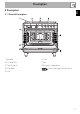
Description EN 2 Description 2.
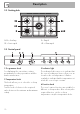
Description 2.2 Cooking hob AUX = Auxiliary SR = Semi-rapid R = Rapid UR = Ultra rapid 2.3 Control panel 1 Programmer clock 3 Indicator light For displaying the current time, setting programmed cooking operations and the minute minder timer. The indicator light comes on to indicate that the oven is heating up. It turns off as soon as it reaches the set temperature. It flashes regularly to indicate that the temperature set inside the oven is kept constant.
5 Hob burner knobs Cooling fan Useful for lighting and adjusting the hob burners. Press and turn the knobs anti-clockwise to the value to light the relative burners. Turn the knobs to the zone between the maximum and minimum setting to adjust the flame. The fan cools the oven and comes into operation during cooking. The fan causes a steady outflow of air that exits from the rear of the appliance and which may continue for a brief period of time even after the appliance has been turned off.
Description 2.5 Available accessories Tray Ring reducers Useful when using small cookware. Tray rack Useful for collecting fat from foods placed on the rack above. Deep tray To be placed over the top of the oven tray; for cooking foods which may drip. Useful for collecting fat from foods placed on the rack above.
Description Self-cleaning panels EN Rotisserie Useful for absorbing small grease residues. Useful for cooking chicken and all foods which require uniform cooking over their entire surface. Rack Some models are not provided with all accessories. The accessories intended to come into contact with food are made of materials that comply with the provisions of current legislation. Supplied and optional accessories can be requested to Authorised Assistance Centres.
Use 3 Use Instructions High temperature inside the oven during use Danger of burns • Keep the oven door closed during cooking. • Protect your hands wearing heat resistant gloves when moving food inside the oven. • Do not touch the heating elements inside the oven. • Do not pour water directly onto very hot trays. • Keep children under the age of 8 away from the appliance when it is in use.
High temperature inside the oven during use Danger of fire or explosion • Do not spray any spray products near the oven. • Do not use or leave flammable materials near the oven or the storage compartment. • Do not use plastic cookware or containers when cooking food. • Do not put sealed tins or containers in the oven. • Do not leave the oven unattended during cooking operations where fats or oils could be released. • Remove all trays and racks which are not required during cooking.
Use 3.1 To save energy 3.2 Using the accessories • Preheat the appliance only if the recipe requires it. • Unless differently stated on the package, defrost frozen food before placing it in the cooking compartment. • In case of multiple cooking, it is recommended to cook food one after the other to exploit the already hot cooking compartment. • Use dark metal moulds: They help to absorb the heat better. • Remove all trays and racks which are not required during cooking.
Racks and trays Rotisserie Racks and trays have to be inserted into the side guides until they come to a complete stop. 1. Insert the 4 supplied bushings in the 4 corner holes of the deep tray and screw them onto the ring nuts with a suitable tool (such as a screwdriver). The mechanical safety locks that prevent the rack from being taken out accidentally have to face downwards and towards the oven back. Gently insert racks and trays into the oven until they come to a stop. EN Use 2.
Use 3. Prepare the rotisserie rod with the food using the clip forks provided. The clip forks can be tightened using the fastening screws. 5. Place the tray on the first runner (see “General Description”). 6. Insert the tip of the rod in the rotisserie motor housing on the left of the rear wall of the oven. 4. Once you have prepared the rotisserie rod, place it on the supports. Insert the tip of the rod in the housing of the mechanism on the left-hand support until it stops.
8. When cooking is complete, remove the tray with the rotisserie. 9. Screw on the handle provided so that you can handle the rotisserie rod more easily. The burner may go out when the knob is released: In this case, the thermocouple has not heated up sufficiently. Wait a few moments and repeat the operation. Keep the knob pressed in longer. In case of an accidental switching off, a safety device will be tripped, cutting off the gas supply, even if the gas cock is open.
Use Practical tips for using the hob 3.5 Using the oven For better burner efficiency and to minimise gas consumption, use pans with lids and of suitable size for the burner, so that the flames do not reach up the sides of the pan. Once the contents come to the boil, turn down the flame far enough to ensure that the liquid does not boil over. Switching on the oven Cookware diameters: • Auxiliary: 12 - 14 cm. • Semi-rapid: 16 - 24 cm. • Rapid: 18 - 26 cm. • Ultra-rapid: 18 - 28 cm. 3.
Fan + lower element The combination of the fan with just the lower heating element allows cooking to be completed more rapidly. This system is recommended for sterilising or for finishing off the cooking of foods which are already well-cooked on the surface, but not inside, which therefore need a little more heat. Perfect for any type of food. In pyrolytic models, the special defrost and proving functions are brought together under the same function.
Use When using the ECO function, avoid opening the door during cooking. Cooking (and preheating) times are longer with the ECO function. The ECO function is a delicate cooking function and is recommended for food withstanding temperatures lower than 210 °C; in case of cooking at higher temperatures, select another function. Vapor Clean This function makes cleaning easier using the steam produced by a small quantity of water poured onto the appropriate groove placed on the bottom. 24 3.
• With the Grill function, we recommend that you turn the temperature knob to the maximum value near the symbol to optimise cooking. • Foods should be seasoned before cooking. Foods should also be coated with oil or melted butter before cooking. • Use the oven tray on the first bottom shelf to collect liquids produced by grilling. Advice for cooking desserts/pastries and biscuits • Use dark metal moulds: They help to absorb the heat better.
Use 3.7 Digital programmer Setting the time If the time is not set, the oven will not switch on. On the first use, or after a power failure, the digits will be flashing on the appliance’s display. 1. Press the keys and at the same time. The dot between the hours and the minutes flashes. Minute minder timer key Cooking duration key End of cooking key Decrease key Value increase key Ensure that the programmer clock shows the cooking duration symbol , otherwise it will not be possible to turn on the oven.
Timed cooking Timed cooking is the function which allows a cooking operation to be started and then ended after a specific length of time set by the user. 1. After selecting a cooking function and temperature, press the key . The display will show the digits and the symbol displayed between the hours and the minutes. 2. Use the key or to set the required minutes. 3. Wait approx. 5 seconds without pressing any key in order for the function to activate.
Use 3. Use the key or to set the required minutes. 4. Wait approx. 5 seconds without pressing any key in order for the function to activate. The current time and the Minute minder timer symbols and will appear on the display. 5. At the end of cooking the heating elements will be deactivated. On the The minute minder timer can be activated at any time. display, the symbol turns off, the symbol flashes and the buzzer sounds. 6. To turn off the buzzer just press any key of the programmer clock. 7.
Use Food Weight (Kg) Function Runner position Temperature from the bottom (°C) EN Cooking information table Time (minutes) Lasagne Pasta bake 3-4 3-4 Static Static 1 1 220 - 230 220 - 230 45 - 50 45 - 50 Roast veal Pork loin Sausages Roast beef Roast rabbit Turkey breast Roast pork neck Roast chicken 2 2 1.5 1 1.5 3 2-3 1.
Cleaning and maintenance 4 Cleaning and maintenance Instructions Improper use Risk of damage to surfaces • Do not use steam jets to clean the appliance. • Do not use cleaning products containing chlorine, ammonia or bleach on parts made of steel or that have metallic surface finishes (e.g. anodizing, nickelor chromium-plating). • Do not use abrasive or corrosive detergents (e.g. scouring powders, stain removers and metallic sponges) on glass parts.
4.1 Cleaning the hob Igniters and thermocouples Cooking hob grids For correct operation the igniters and thermocouples must always be perfectly clean. Check them frequently and clean them with a damp cloth if necessary. Remove any dry residues with a wooden toothpick or a needle. Remove the grids and clean them in lukewarm water and non-abrasive detergent. Make sure to remove any encrustations. Dry them thoroughly and return them to the hob.
Cleaning and maintenance 4.2 Cleaning the door Removing the door For easier cleaning, the door can be removed and placed on a canvas. To remove the door proceed as follows: 1. Open the door completely and insert two pins into the holes on the hinges indicated in the figure. 3. To reassemble the door, put the hinges in the relevant slots in the oven, making sure that grooved sections A are resting completely in the slots. Lower the door and once it is in place remove the pins from the holes in the hinges.
Removing the internal glass panes For easier cleaning the internal glass panes of the door can be removed. 1. Open the door. 2. Position the retaining clips in the holes in the hinges in order to prevent accidental closing of the door. 3. Pull the rear part of the internal glass pane gently upwards, following the movement indicated by the arrows (1). 5. Remove the intermediate glass pane by lifting it upwards. 6. Clean the external glass pane and the panes removed previously. Use absorbent kitchen roll.
Cleaning and maintenance 4.3 Cleaning the oven cavity In order to keep your oven in the best possible condition, clean it regularly after letting it cool down. Avoid letting food residue dry inside the oven cavity, as this could damage the enamel. Take out all removable parts before cleaning. For easier cleaning, we recommend removing: • The door • The rack/tray support frames • The seal.
Regeneration of self-cleaning panels (catalytic cycle) The regeneration cycle of the self-cleaning panels is a cleaning method through heating suitable for removing small grease residues, not sugar-based ones. 1. Clean the base and the upper section first with a microfibre cloth soaked in water and neutral washing up liquid. Rinse thoroughly. 2. Set a regeneration cycle by selecting a fan assisted function at the maximum temperature for one hour. 3.
Cleaning and maintenance • Pour approximately 40 cc of water into the tray. Make sure it does not overflow out of the cavity. Vapor Clean setting 1. Turn the function knob to the symbol the temperature knob to the symbol and . 2. Set a cooking time of 18 minutes using the programmer clock. The Vapor Clean cycle starts a few seconds after the last press on the programmer clock keys. 3.
End of the Vapor Clean cycle 4.5 Extraordinary maintenance 4. Open the door and wipe away the less stubborn dirt with a microfibre cloth. 5. Use an anti-scratch sponge with brass filaments on tougher encrustations. 6. In case of grease residues use specific oven cleaning products. 7. Remove the water left inside the oven. For improved hygiene and to avoid food being affected by any unpleasant odours, we recommend that the oven is dried using a fan assisted function at 160 °C for approximately 10 minutes.
Cleaning and maintenance Replacing the internal light bulb 4. Slide out and remove the light bulb. Live parts Danger of electrocution • Unplug the appliance. The oven is fitted with a 40W light bulb. 1. Completely remove all accessories from inside the oven. 2. Remove the rack/tray support frames. 3. Remove the bulb cover using a tool (e.g. a screwdriver). Do not touch the halogen lamp directly with your fingers, but wrap it in an insulating material. 5. Fit the new light bulb. 6. Refit the cover.
5 Installation 5.1 Gas connection Gas leak Danger of explosion • After carrying out any operation, check that the tightening torque of gas connections is between 10 Nm and 15 Nm. • If required, use a pressure regulator that complies with current regulations. • At the end of the installation, check for any leaks with a soapy solution, never with a flame. • Installation using a hose must be carried out so that the length of the hose does not exceed 2 metres when fully extended for steel hoses and 1.
Installation Carefully screw the hose connector 3 to the appliance’s gas connector 1 (½” thread ISO 228-1), placing the seal 2 between them. The hose connector 4 can also be screwed to the hose connector 3, depending on the diameter of the gas hose used. After having tightened the hose connector(s), push the gas hose 6 onto the hose connector and secure it with the clamp 5 that is compliant with the standard in force.
Connection to LPG Room ventilation Use a pressure regulator and make the connection on the gas cylinder following the guidelines set out in the standards in force. The appliance should be installed in rooms that have a permanent air supply in accordance with the standards in force. The room where the appliance is installed must have enough air flow for the regular combustion of gas and the necessary air change in the room itself.
Installation An efficient extraction system requires precision planning by a specialist qualified in this area and must comply with the positions and clearances indicated by the applicable standards. When the job is complete, the installer must issue a certificate of conformity. 5.
(see "Nozzle and burner specification tables"). Adjusting the minimum setting for LPG Tighten the screw located at the side of the cock rod clockwise all the way. Following adjustment to a gas other than the one originally set in the factory, replace the gas setting label on the appliance with the one corresponding to the new gas. The label is inserted inside the nozzle pack (where present). 3. Reposition the burners in their respective housings.
Installation Gas types and Countries Gas types 1 Natural Gas G20 G20 20 mbar G20/25 20/25 mbar 2 Natural Gas G20 G20 25 mbar 3 Natural Gas G25 G25 25 mbar 4 Natural Gas G25.1 G25.1 25 mbar 5 Natural Gas G25 G25 20 mbar 6 Natural Gas G27 G27 20 mbar 7 Natural Gas G2.350 G2.
Installation 1 Natural Gas G20 Rated heating capacity (kW) Nozzle diameter (1/100 mm) Pre-chamber (printed on nozzle) Reduced flow rate (W) 2 Natural gas G20 – 25 mbar Rated heating capacity (kW) Nozzle diameter (1/100 mm) Pre-chamber (printed on nozzle) Reduced flow rate (W) 3 Natural gas G25 – 25 mbar Rated heating capacity (kW) Nozzle diameter (1/100 mm) Pre-chamber (printed on nozzle) Reduced flow rate (W) 4 Natural gas G25.
Installation 8 LPG G30/31 Rated heating capacity (kW) Nozzle diameter (1/100 mm) Pre-chamber (printed on nozzle) Reduced flow rate (W) Rated flow rate G30 (g/h) Rated flow rate G31 (g/h) 9 LPG G30/G31 – 37 mbar Rated heating capacity (kW) Nozzle diameter (1/100 mm) Pre-chamber (printed on nozzle) Reduced flow rate (W) Rated flow rate G30 (g/h) Rated flow rate G31 (g/h) 10 LPG G30/G31 – 50 mbar Rated heating capacity (kW) Nozzle diameter (1/100 mm) Pre-chamber (printed on nozzle) Reduced flow rate (W) Rated
5.3 Positioning Heavy appliance Crushing hazard • Position the appliance into the cabinet cut-out with the help of a second person. Pressure on the open door Risk of damage to the appliance • Never use the oven door to lever the appliance into place when fitting. • Avoid exerting too much pressure on the oven door when open. Any wall units installed above the appliance’s worktop must be positioned at least Y mm from it.
Installation Appliance overall dimensions B - Class 2 subclass 1 (Built-in appliance) A 900 mm B 600 mm C1 D min. 150 mm 900 - 915 mm H 750 mm I 450 mm L2 900 mm 1 Minimum distance from side walls or other flammable material. 2 Minimum cabinet width (=A). C - Class 2 subclass 1 (Built-in appliance) The appliance must be installed by a qualified technician and according to the regulations in force.
Dimensions of the appliance: locations of gas and electric connections (mm) Positioning and levelling Heavy appliance Risk of damage to the appliance • Insert the front feet first and then the rear ones. • After making the gas and electrical connections, screw on the four feet supplied with the appliance. A 124 B 38 C 42 D 634 F min. 105 - max. 160 H 776 L 898 E = Electrical connection G = Gas connection The appliance must sit level on the floor to ensure stability.
Installation Fastening to the wall 3. Assemble the fastening bracket. The anti-tip devices must be installed in order to prevent the appliance tipping over. 1. Screw the wall fastening plate to the rear of the appliance. 4. Align the base of the hook on the fastening bracket with the base of the slot on the wall fastening plate. 2. Adjust the height of the 4 feet.
Installation 6. Use 50 mm for the distance from the side of the appliance to the bracket holes. 7. Move the bracket onto the wall and mark the position of the holes to be drilled in the wall. EN 5. Align the base of the fastening bracket with the ground and tighten the screws to fix the measurements. 8. After drilling the holes in the wall, use wall plugs and screws to fasten the bracket to the wall. 9.
Installation Assembling the upstand The upstand provided is an integral part of the product. It must be fastened to the appliance prior to installation. The upstand must always be positioned and secured correctly on the appliance. 1. Unscrew the 2 nuts B on the back of the worktop. 2. Position the upstand above the worktop, taking care to align the pins C with the holes D. 3. Secure the upstand to the worktop by tightening the screws A. 5.
The appliance can work in the following modes: • 220-240 V 1N~ 3 x 1.5 mm² three-core cable. The values indicated above refer to the cross-section of the internal conductor. The aforementioned power cables are sized taking into account the coincidence factor (in compliance with standard EN 60335-2-6). Fixed connection Fit the power line with an omnipolar circuit breaker in compliance with installation regulations.
Installation 5.5 Instructions for the installer • The plug must be accessible after installation. Do not bend or trap the power cable. • The appliance must be installed according to the installation diagrams. • Do not try to unscrew or force the threaded elbow of the fitting. You may damage this part of the appliance, which may void the manufacturer’s warranty. • Use soap and water to check for gas leaks on all connections. DO NOT use naked flames when looking for leaks.