Table of contents 1.1 1.2 1.3 1.4 1.5 1.6 1.7 4 General safety instructions Manufacturer liability Appliance purpose Identification plate This user manual Disposal How to read the user manual 2 Description 2.1 2.2 2.3 2.4 2.5 General Description Cooking hob Control panel Other parts Available accessories Instructions Cleaning the surfaces Cleaning the hob Cleaning the door Cleaning the oven cavity Extraordinary maintenance 5 Installation 5.1 5.2 5.3 5.4 5.
Instructions 1 Instructions 1.1 General safety instructions Risk of personal injury • During use the appliance and its accessible parts become very hot. Never touch the heating elements during use. • Protect your hands by wearing oven gloves when moving food inside the oven. • Never try to put out a fire or flames with water: turn off the appliance and smother the flames with a fire blanket or other appropriate cover.
• If you need to move food or at the end of cooking, open the door 5 cm for a few seconds, let the steam come out, then open it fully. • Do not open the storage compartment (where present) when the oven is on and still hot. • The items inside the storage compartment could be very hot after using the oven. • DO NOT USE OR STORE FLAMMABLE MATERIALS IN THE STORAGE COMPARTMENT (IF AVAILABLE) OR NEAR THE APPLIANCE. • DO NOT USE AEROSOLS IN THE VICINITY OF THIS APPLIANCE WHILST IT IS IN USE.
Instructions • Never leave the appliance unattended during cooking operations where fats or oils could overheat and take fire. Be very careful • Never leave objects on the cooking surface. • DO NOT USE THE APPLIANCE TO HEAT ROOMS FOR ANY REASON. • Do not spray any spray products near the oven. • Do not use plastic cookware or containers for cooking. • Do not place sealed tins or containers in the oven cavity. • Remove all trays and racks which are not required during cooking.
• Do not use the handle to lift or move this appliance. Installation • THIS APPLIANCE MUST NOT BE INSTALLED IN A BOAT OR CARAVAN. • This appliance must not be installed on a pedestal. • Position the appliance into the cabinet cut-out with the help of a second person. • To prevent any possible overheating, the appliance should not be installed behind a decoration door or a panel. • Have the gas connection performed by authorised staff.
Instructions For this appliance • Ensure that the appliance is switched off before replacing the bulb. • Do not rest any weight or sit on the open door of the appliance. • Take care that no objects are stuck in the doors. 1.
Instructions Power voltage Danger of electrocution • Disconnect the mains power supply. • Unplug the appliance. • Deliver the appliance to the appropriate recycling centre for electrical and electronic equipment waste, or return it to the retailer when purchasing an equivalent product, on a one for one basis. Our appliances are packaged in non-polluting and recyclable materials. • Deliver the packing materials to the appropriate recycling centre. EN 1.
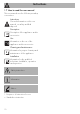
Instructions 1.7 How to read the user manual This user manual uses the following reading conventions: Instructions General information on this user manual, on safety and final disposal. Description Description of the appliance and its accessories. Use Information on the use of the appliance and its accessories. Cleaning and maintenance Information for proper cleaning and maintenance of the appliance. Installation Information for the qualified technician: Installation, operation and inspection.
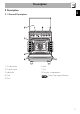
Description EN 2 Description 2.
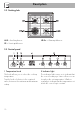
Description 2.2 Cooking hob AUX = Auxiliary burner SR = Semi-rapid burner UR-3c = Ultra-rapid burner 2.3 Control panel 1 Temperature knob 2 Indicator light This knob allows you to select the cooking temperature. Turn the knob clockwise to the required value, between the minimum and maximum setting. The indicator light comes on to indicate that the oven is heating up. It turns off as soon as it reaches the set temperature.
Description 3 Function knob EN Cooling fan The oven’s various functions are suitable for different cooking modes. After selecting the required function, set the cooking temperature using the temperature knob. 4 Programmer clock (on some models only) Useful for displaying the current time, setting programmed cooking operations and programming the minute minder timer. Intermediate positions between the figures can be used. The minute minder timer only activates the buzzer, without stopping cooking.
Description 2.5 Available accessories Lid Rack Useful for supporting containers with food during cooking. Deep tray The toughened glass lid with aluminium edging protects the hob when not in use. Not all accessories are available on some models. The oven accessories intended to come into contact with food are made of materials that comply with the provisions of current legislation. Useful for collecting fat from foods placed on the rack above and for cooking pies, pizzas and baked desserts.
Use 3.1 Instructions High temperature inside the oven during use Danger of burns • Keep the oven door closed during cooking. • Protect your hands wearing heat resistant gloves when moving food inside the oven. • Do not touch the heating elements inside the oven. • Do not pour water directly on very hot trays. • Keep children under the age of 8 away from the oven when it is in use.
Use High temperature inside the storage compartment Danger of fire or explosion • Do not spray any spray product near the appliance. • Do not use or leave flammable materials near the appliance or the storage compartment. • Do not use plastic cookware or containers for cooking. • Do not place sealed tins or containers in the oven cavity. • Do not leave the appliance unattended during cooking operations where fats and oils could be released. • Remove all trays and racks which are not required during cooking.
First use Racks and trays 1. Remove any protective film from the outside or inside of the appliance, including accessories. 2. Remove any labels (apart from the technical data plate) from the accessories and from the oven cavity. 3. Remove and wash all the appliance's accessories (see 4 Cleaning and maintenance). 4. Heat the empty oven at the maximum temperature to burn off any residues left by the manufacturing process.
Use 3.3 Using the hob All the appliance’s control and monitoring devices are located together on the front panel. The burner controlled by each knob is shown next to the knob. The appliance is equipped with an electronic ignition device. Simply press the knob and turn it counterclockwise to the maximum flame symbol, until the burner ignites. If the burner does not light in the first 15 seconds, turn the knob to and wait 60 seconds before trying again.
3.4 Using the oven Switching on the oven (models with programming clock) To switch the oven on: 1. Select the cooking function using the function knob. 2. Select the temperature using the temperature knob. Ensure that the programmer clock shows the cooking duration symbol , otherwise it will not be possible to turn on the oven. Press the keys and at the same time to reset the programmer clock.
Use Fan assisted The operation of the fan, combined with traditional cooking, ensures consistent cooking even with complex recipes. Perfect for biscuits and cakes, even when simultaneously cooked on several levels. (For multiple-level cooking, we recommend using the 2nd and 4th runners).
Use Setting the time EN 3.5 Programmer clock If the time is not set, the oven will not switch on. On the first use, or after a power failure, the digits will be flashing on the appliance’s display. 1. Press the keys and at the same time. The dot between the hours and the minutes flashes. Minute minder timer key Cooking duration key End of cooking key. Decrease key Increase key Ensure that the programmer clock shows the cooking duration symbol , otherwise it will not be possible to turn on the oven. 2.
Use Timed cooking Timed cooking is the function which allows a cooking operation to be started and then ended after a specific length of time set by the user. 1. After selecting a cooking function and temperature, press the key. The display will show the digits and the symbol displayed between the hours and the minutes. 2. Use the or key to set the required minutes. 3. Wait approx. 5 seconds without pressing any key in order for the function to activate.
Use Programmed cooking is the function which allows a cooking operation to be started at a set time and then ended after a specific length of time set by the user. 1. Set the cooking time as described in the previous point “Timed cooking”. 2. Press the key. The sum of the current time plus the pre-set cooking duration will appear on the display. 3. Use the or key to set the required minutes. 4. Wait approx. 5 seconds without pressing any key in order for the function to activate.
Use Minute minder timer The minute minder timer does not stop the cooking operation but rather informs the user when the set time has run out. The minute minder timer can be activated at any time. 1. Press the key. The display shows the digits and the indicator light flashing between the hours and the minutes. 2. Use the or key to set the required minutes. 3. Wait approx. 5 seconds without pressing any key to finish setting the minute minder. The current time and the symbols and appear on the display.
3.7 Cooking advice General advice • Use a fan assisted function to achieve consistent cooking at several levels. • It is not possible to shorten cooking times by increasing the temperature (the food could be overcooked on the outside and undercooked on the inside). • For the same total weight, cooking time will be greater for cooking a whole piece than when it is cut into smaller pieces. Advice for cooking meat • Cooking times vary according to the thickness and quality of the food and to consumer taste.
Use Advice for defrosting and proving To save energy • Place frozen foods without their packaging in a lidless container on the first shelf of the oven. • Avoid overlapping the food. • To defrost meat, use the rack placed on the second level and a tray on the first level. In this way, the liquid from the defrosting food drains away from the food. • Bread and fruit, if divided into pieces, will take the same amount of time to defrost, regardless of the total weight and quantity.
Use EN Cooking information table Weight (kg) Function Shelf Temperature (°C) Lasagne Pasta bake 3-4 3-4 Static Static 1 1 220 - 230 220 - 230 45 - 50 45 - 50 Roasted veal Pork loin Sausages Roast beef Roast rabbit Turkey breast Roast pork neck Roast chicken 2 2 1.5 1 1.5 3 2-3 1.
Cleaning and maintenance 4 Cleaning and maintenance 4.1 Instructions Improper use Risk of damage to surfaces • Do not use steam jets to clean the appliance. • Do not use cleaning products containing chlorine, ammonia or bleach on parts made of steel or that have metallic surface finishes (e.g. anodizing, nickelor chromium-plating). • Do not use abrasive or corrosive detergents (e.g. scouring powders, stain removers and metallic sponges) on glass parts.
4.3 Cleaning the hob Flame-spreader crowns and burner caps Knobs For easier cleaning, the flame-spreader crowns and the burner caps can be removed. Wash them in hot water and nonabrasive detergent. Carefully remove any encrustation, then wait until they are perfectly dry. Refit the flame-spreader crowns making sure that they are correctly positioned in their housings with their respective burner caps.
Cleaning and maintenance Glass lid For easier cleaning, the lid can be taken off its hinges. 1. Lower the lid to closed position. 3. Open it and lift it upwards. 4. Clean. 5. Insert the lid into the guides. Tighten the fastening screws on the hinges in closed position. If liquids fall on the lid when it is closed, carefully remove them with a cloth before opening it. Knobs 2. Unscrew the screws on the back of the hinges.
4.4 Cleaning the door Removing the door For easier cleaning, the door can be removed and placed on a towel. To remove the door proceed as follows: 1. Open the door completely and insert two pins into the holes on the hinges indicated in the figure. 3. To reassemble the door, put the hinges in the relevant slots in the oven, making sure that grooved sections A are resting completely in the slots. Lower the door and once it is in position, remove the pins from the holes in the hinges.
Cleaning and maintenance Removing the internal glass panes For easier cleaning, the internal glass panes of the door can be removed. 1. Remove the internal glass pane by pulling the rear part gently upwards following the movement indicated by the arrows (1). This way, the 4 pins attached to the glass detach from their housings in the door. 2. Then, pull the front part upwards (2). 3. Remove the intermediate glazing pane by lifting it upwards.
4.5 Cleaning the oven cavity Cleaning of racks and trays For the best oven cavity upkeep, clean it regularly after having allowed it to cool. Avoid letting food residue dry inside the oven cavity, as this could damage the enamel. Take out all removable parts. Clean the racks and trays with warm water and non-abrasive detergents. Carefully rinse and dry damp parts. Removing racks/trays support frames Removing the guide frames enables the sides to be cleaned more easily.
Cleaning and maintenance Vapour Clean Vapor Clean is an assisted cleaning procedure which facilitates the removal of dirt. Thanks to this process, it is possible to clean the inside of the oven very easily. The dirt residues are softened by the heat and water vapour for easier removal afterwards. Improper use Risk of damage to surfaces • Remove any food residues or large spills from previous cooking operations from the inside of the oven.
Vapor Clean cycle setting 4.6 Extraordinary maintenance 1. Turn the function knob to the symbol and the temperature knob to the symbol Installing and removing the seal . 2. Set a cooking time of 18 minutes using the programmer clock. 3. At the end of the cooking time, the timer will switch the oven heating elements off and the buzzer will start to sound. EN Cleaning and maintenance To remove the seal: • Unhook the clips in the 4 corners then pull the seal outwards. End of the Vapor Clean cycle 4.
Cleaning and maintenance Replacing the internal light bulb 4. Slide out and remove the light bulb. Live parts Danger of electrocution • Unplug the appliance from the mains. • Wear protective gloves. 1. Remove all accessories from inside the oven cavity. 2. Remove the rack/tray support frames. 3. Remove the bulb cover using a tool (e.g. a screwdriver). Take care not to scratch the enamel of the oven cavity wall. Do not touch the halogen light bulb directly with your fingers, use an insulating material. 5.
5 Installation 5.1 Gas connection (not valid for the UK) For installation in the UK, please refer to the “Local specifications for UK gas appliances installation” booklet. Gas leak Danger of explosion General information Connection to the gas mains can be made using a continuous wall steel hose in compliance with the guidelines established by the standards in force. The appliance is preset for natural gas G20 (2H) at a pressure of 20 mbar. For supplying it with other types of gas, see chapter “5.
Installation Carefully screw the hose connector 3 to the appliance’s gas connector 1 (½” thread ISO 228-1), placing the seal 2 between them. The hose connector 4 can also be screwed to the hose connector 3, depending on the diameter of the gas hose used. After having tightened the hose connector(s), push the gas hose 6 onto the hose connector and secure it with the clamp 5 that is compliant with the standard in force.
Connection to LPG Room ventilation Use a pressure regulator and make the connection on the gas cylinder following the guidelines set out in the standards in force. The appliance should be installed in rooms that have a permanent air supply in accordance with the standards in force. The room where the appliance is installed must have enough air flow for the regular combustion of gas and the necessary air change in the room itself.
Installation 5.2 Adaptation to different types of gas Improper installation Risk of malfunction • In the case of conversion to Town Gas G110 – 8 mbar (category 1a), do not use the burners provided, but request the special G110 burners kit from our Technical Assistance Service.
(see "Nozzle and burner specification tables"). Adjusting the minimum setting for LPG Tighten the screw located at the side of the cock rod clockwise all the way. Following adjustment to a gas other than the one originally set in the factory, replace the gas setting label on the appliance with the one corresponding to the new gas. The label is inserted inside the nozzle pack (where present). 3. Reposition the burners in their respective housings.
Installation Gas types and Countries EN GB-IE FR-BE DE AT NL ES PT SE RU DK PL HU Gas types 1 Natural gas G20 G20 20 mbar • • • • • • • • • • G20/25 20/25 mbar 2 Natural gas G20 G20 • 25 mbar 3 Natural gas G25 G25 25 mbar G25.3 25 mbar • • 4 Natural gas G25.1 G25.1 • 25 mbar 5 Natural gas G25 G25 • 20 mbar 6 Natural gas G27 G27 • 20 mbar 7 Natural gas G2.350 G2.
Installation 1 Natural gas G20 Rated heating capacity (kW) Nozzle diameter (1/100 mm) Pre-chamber (printed on nozzle) Reduced flow rate (W) 2 Natural gas G20 Rated heating capacity (kW) Nozzle diameter (1/100 mm) Pre-chamber (printed on nozzle) Reduced flow rate (W) 3 Natural gas G25 Rated heating capacity (kW) Nozzle diameter (1/100 mm) Pre-chamber (printed on nozzle) Reduced flow rate (W) 4 Natural gas G25.
Installation 8 LPG G30/31 Rated heating capacity (kW) Nozzle diameter (1/100 mm) Pre-chamber (printed on nozzle) Reduced flow rate (W) Rated flow rate G30 (g/h) Rated flow rate G31 (g/h) 9 LPG G30/31 Rated heating capacity (kW) Nozzle diameter (1/100 mm) Pre-chamber (printed on nozzle) Reduced flow rate (W) Rated flow rate G30 (g/h) Rated flow rate G31 (g/h) 10 LPG G30/31 Rated heating capacity (kW) Nozzle diameter (1/100 mm) Pre-chamber (printed on nozzle) Reduced flow rate (W) Rated flow rate G30 (g/h) Ra
5.3 Positioning Heavy appliance Crushing hazard • Position the appliance into the cabinet cut-out with the help of a second person. Pressure on the open door Risk of damage to the appliance • Never use the oven door to lever the appliance into place when fitting. • Avoid exerting too much pressure on the door when open. Any wall units positioned above the worktop of the appliance must be at a minimum distance of at least Y mm.
Installation Appliance overall dimensions B - Class 2 subclass 1 (Built-in appliance) A 600 mm B 600 mm C1 D min. 150 mm 900 - 915 mm H 750 mm I 450 mm L2 600 mm 1 Minimum distance from side walls or other flammable material. 2 Minimum cabinet width (=A). C - Class 2 subclass 1 (Built-in appliance) The appliance must be installed by a qualified technician and according to the regulations in force.
Dimensions of the appliance: locations of gas and electric connections (mm) Positioning and levelling Heavy appliance Risk of damage to the appliance • Insert the front feet first and then the rear ones. After making the electrical and/or gas connections, screw the four adjustable feet supplied with the appliance. A 124 B 32 C 42 D 628 F min. 70 - max. 110 H 770 L 598 The appliance must sit level on the floor to ensure stability.
Installation Fastening to the wall 3. Assemble the fastening bracket. The anti-tip devices must be installed in order to prevent the appliance from tipping over. 1. Screw the wall fastening plate to the rear of the appliance. 2. Adjust the height of the 4 feet. 48 4. Align the base of the hook on the fastening bracket with the base of the slot on the wall fastening plate.
Installation 6. Use 50 mm for the distance from the side of the appliance to the bracket holes. 7. Move the bracket onto the wall and mark the position of the holes to be drilled in the wall. EN 5. Align the base of the fastening bracket with the ground and tighten the screws to fix the measurements. 8. After drilling the holes in the wall, use wall plugs and screws to fasten the bracket to the wall. 9.
Installation Fitting the lid 3. Lower the lid onto the hob. 1. Install the two supports A and fasten them from below the hob using the corresponding screws B. 4. Fasten the lid to the hob using the screws C inserted in the rear of the two supports A. 2. Install the lid from above, parallel with the two supports A.
Installation Power voltage Danger of electrocution • Have the electrical connection performed by authorised technicians. • Use personal protective equipment. • The appliance must be connected to ground in compliance with electrical system safety standards. • Disconnect the mains power supply. • Do not pull the cable to remove the plug. • Use cables withstanding a temperature of at least 90 °C. • The tightening torque of the screws of the terminal board leads must be 1.5 - 2 Nm.
Installation 5.5 Instructions for the installer • The plug must be accessible after installation. Do not bend or trap the power cable. • The appliance must be installed according to the installation diagrams. • Do not try to unscrew or force the threaded elbow of the fitting. You may damage this part of the appliance, which may void the manufacturer’s warranty. • Use soap and water to check for gas leaks on all connections. DO NOT use naked flames when looking for leaks.