USER MANUAL
Index Page 2 1 1.1 1.2 1.3 Important directions for safety and the environment For your safety Caring for the environment Cleaning, sanitization and maintenance of the ice and/or water dispenser (if present) 4 2 2.1 2.2 2.3 Installation Installation Connection to the electrical power supply Connection to the water system 6 3 3.1 3.2 3.3 3.4 3.5 Before starting Know your appliance Main features Main components Electronic Control Main control panel 10 4 4.1 4.2 4.3 4.
1 Important directions for safety and the environment 1.1 For your safety If this appliance is replacing an existing appliance which must be removed or disposed of, make sure that it does not become a dangerous trap for children by cutting its power supply cable and rendering it impossible to close the door. Use the same caution at the end of the lifespan of the new appliance. Risk Group 2 This appliance is designed to refrigerate beverages and foods and is intended for domestic use.
Important directions for safety and the environment Caring for the environment 1 1.2 Pay special attention to correct disposal procedure for all the packaging materials. The appliance must not be disposed of with urban waste. Contact local waste disposal centers for on how to dispose of recyclable waste. Prior to disposal, cut the power supply cord and make it impossible to close the door. During disposal, avoid damage to the refrigeration circuit.
2 2.1 Installation Installation Make sure that installation is performed correctly, adhering to all directions in the specific installation manual provided with the appliance. 2.2 Connection to the electrical power supply The appliance is equipped with a Schuko type 16A plug and must be connected to the electrical power supply through a corresponding Schuko socket. Do not use extension cords and/or multiple adapters for the power supply connection.
Installation 2 Connection to the water system 2.3 The models provided with Ice Maker require a connection to the domestic water supply system. This can be executed through the provided water hose with 3/4” threading. The system pressure must be between 0.05 MPa and 0.5 MPa (between 0.5 Bar and 5 Bar). Differents pressures can cause malfunctions or leaks in the water system. The appliance should be supplied only with drinkable water. The appliance should be supplied only with drinkable water.
3 Before starting 3.1 Know your appliance Congratulations for having purchased your new Smeg: from now on you can use our innovative conservation system, which will allow you to keep all of your food in the best way possible. This manual will answer most of your questions about the product’s features. Should you require further information, please check our website www.smeg.com 3.
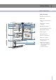
Before starting 3 Main components 3.
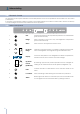
3 Before starting 3.4 Electronic Control Componenti principali 3.3 The electronic control system maintains constant temperature on the two compartments and visualizes it on the control panel display. It also allows user interaction making it possible to personalize settings of the various functions and to receive sound and/ or visual messages should occur any malfunction in the appliance. 3.5 Main control panel 1 8 Componenti principali 3.
Appliance switching on and off 4 Switching on and off 4.1 First startup When the appliance is connected to the electrical power supply but has not yet been switched on, the display shows the message Tis is a safety message to warn that the appliance is connected to the mains, and all the panel buttons are off. To switch on all the appliance compartments, press the Unit button for three seconds.
4 Appliance switching on and off 4.2 How to adjust the temperature for different requirements Each model has been carefully tested before leaving the factory and is adjusted in such a way to ensure high performance and low consumption. Usually, it is not necessary to modify the settings. Nevertheless, according to special needs, it is possible to modify the set temperatures as follows: Refrigeration Compartment From +2°C to +8°C (from 35.6°F to 46.4°F), the recommended preset temperature is +5°C (41°F).
Settings and Special Functions 5 Customization and language settings 5.1 It is possible to customized the functions of your Smeg to adapt it to diverse usage needs, resetting the main parameters (Settings) or activating special functions (Functions). To prevent an inadvertent change to the settings the keypad is automatically locked after a certain period of time. To re-activate the Menu function, press simultaneously the Menu button and the Down button for at least three seconds.
5 Settings and Special Functions Holiday fridge Holiday Fridge This function (recommended in case of prolonged absences since it allows considerable energy savings) brings the refrigerator compartment temperature to +14°C (57.2°F). It is possible to program the duration, or it can be manually deactivated upon re-entry after a period of absence. This function remains active even if during the period of absence there is a prolonged interruption of electrical power.
Settings and Special Functions Holiday Multizone How to activate How to deactivate upon re-entry How to program the duration 5 This function (recommended in case of prolonged absences since it allows considerable energy savings) brings the Multizone compartment temperature to - 18°C (46.4°F). It is possible to program the duration, or it can be manually deactivated upon re-entry after a period of absence.
5 Settings and Special Functions Sabbath Mode (Optional) How to activate How to deactivate Water Filter How to check the status of the filter Reset Filter How to set the filtered water meter to zero Bypass Filter How to activate filter Bypass How to deactivate filter Bypass Manual Clean, Water Filter How to manually clean the filter Correctly position the ice tray or another suitable container under the IceMaker to collect water, then close the drawer.
Settings and Special Functions 5 Basic settings of the Menu 5.3 Select the Menu button . Multizone Options and used the Up/Down button The freezer compartment can, if required, be converted to the refrigeration o 0°C operating mode.
5-6 Internal Layout Set 12/24 This function selects the display at 12 or 24 h. How to set the display to 12 h Settings Set: 12 Time Set View How to set the display to 24 h Settings Set: 24 Time Set View Show Time Through this function it is possible to activate/deactivate the constant visualization of the time.
Internal Layout 6 Multizone Drawer The upper Multizone can be removed using the same method used for the 0°C drawer to remove the inner Multizone drawer unscrew the thumbscrews. When replacing the drawers, make certain the back of the drawers engage under the clips on the slide guides. Ice Tray Located in the upper drawer of the freezer compartment after removal, make sure to reposition it correctly. Do not place hands or fingers near the Icemaker when in function.
7 Activation and use of the Ice Maker 7.1 Activation and use of the Ice Maker If the ice is not used frequently is advisable to empty the ice bin once every 8-10 days. To activate the Ice Maker after installation of the appliance, press the Icemaker button . It is normal that some ice cubes stick to one another. If the ice is not frequently used, the older cubes can become opaque, and will have a strange flavor and become smaller.
Activation and use of the Ice Maker 7 Water Filter 7.2 The Water Filter makes available high-quality water for the production of ice cubes. It provides up to 3000 liters of water for a maximum time of 12 months. On some models, on the upper right of the control panel it is possible to monitor the use status of the filter: when the entire area is illuminated the filter has just been replaced; the white illuminated area indicates that the filter capacity is below 20%.
8 Lighting 8.1 Lighting To provide optimum interior lighting, LED strips illuminate the refrigerator compartment from the top and sets of LED lights directly illuminate different areas of the refrigerator compartment and the freezer drawer. In case of malfunction and/or wearing out of the lighting system, the repair should be carried out by a qualified Smeg Service technician.
Vegetables Fruit Packaged meat Food Preservation 9 Recommendations for preserving fresh food 9.1 Wash vegetables in cold water and dry well. Place vegetables in vacuum packed containers, plastic containers or vegetable bags in a 0°C Drawer. Wash and dry fresh fruit. Pack very aromatic fruit in plastic bags. Fruit should be placed in the high humidity 0°C compartment. Place in the refrigerator in its original packaging. After opening, wrap the remaining food in plastic bags or aluminum foil.
10 Recommended times for Food Preservation Fresh foods Preservation area Time Raw meats Large cuts 0°C Compartment 4 days Beef steaks, poultry and wild game 0°C Compartment 3 days Ground meat 0°C Compartment 1-2 days Carpaccio 0°C Compartment Immediately Boiled meat and roasted meat Refrigerator Compartment 2 days Meat sauce Refrigerator Compartment 6 days 0°C Compartment 2 days Soups and broths Refrigerator Compartment 2 days Pasta Refrigerator Compartment 2 days Opened cold cu
Care and Cleaning 11 Care and Cleaning 11.1 To clean the parts made of steel use a microfiber cloth and the sponge provided in the kit with the appliance. Always use the cloth and sponge in the direction of the steel’s satin finish. Scrupulously follow the detailed directions that can be found in the provided kit and never use abrasive or metallic products which could scratch and damage the satin finishing on the appliance permanently.
12 Troubleshooting Guide 12.1 Troubleshooting Guide If you notice malfunctions in your appliance, use this guide before calling for service: this guide can help you personally resolve the problem or could provide important information to be conveyed to the service technician to ensure rapid and effective repair. Malfunction message The refrigerator or the freezer does not work The refrigerator or the freezer is warmer than usual 24 A malfunction is usually indicated by a message on the display.
Troubleshooting Guide The Ice Maker does not work 12 Make sure that the Ice Maker is on (Icemaker button on). To switch on the Ice Maker press the button. Make sure that the appliance is connected to the water supply. The Ice Maker does not produce sufficient amounts of ice On average, the Ice Maker produces approximately 10 cubes of ice every two and half hours. The ice cubes freeze into one block If the ice is not used frequently, it is possible that blocks of ice may form.
13 Smeg Access Menu Map 13.
Smeg Access Menu Map 13 Setting 13.
22-12-2014
SMEG EN
I N S TA L L AT I O N G U I D E
IMPORTANT Dimensions in parentheses are in inches. Weights in parentheses are in pounds. Temperatures in parentheses are in Fahrenheit degrees.
Installation Guide Index Important Instructions Page 2 Important safety instructions Children safety Technical requirements 4 Appliance features and installation requirements 5 Installation niche features: Integrated 6 Installation niche features: Free-Standing Preparing to install 7 Transport to installation site and unpacking 8 Electrical and Water connection 11 Levelling Panels mounting 12 Decorative door and Bottom-Drawer panels layout 14 Decorative panels layout for Fridge with one Bo
2
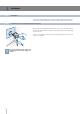
Installation Guide Important safely instruction Symbols used in the Guide Note Tips for the correct use of the appliance Important Directions to avoid appliance damage Warning directions to prevent injury Children safety If this appliance is replacing an existing appliance which must be removed or disposed of, make sure that it does not become a dangerous trap for children by cutting its power supply cable and rendering it impossible to close the door.
Appliance features and installation requirements Appliance dimensions Integrated 60 Series 75 Series 90 Series w: 599 mm (23 5/8”)/ h: 2050 mm (80 3/4”)/ d: 610 mm (24”) w: 749 mm (29 1/2”)/ h: 2050 mm (80 3/4”)/ d: 610 mm (24”) w: 899 mm (35 3/8”)/ h: 2050 mm (80 3/4”)/ d: 610 mm (24”) Appliance dimensions Free-Standing 60 Series 75 Series 90 Series w: 586 mm (23”)/ h: 2120 mm (84”)/ d: 635 mm (25”) w: 736 mm (29”)/ h: 2120 mm (84”)/ d: 635 mm (25”) w: 8869 mm (34 7/8”)/ h: 2120 mm (84”)/ d: 635 mm (2
Installation Guide Installation niche features: Integrated Series A area to be left clear for the anti-tipping brackets Door Opening Angle E area to be left clear for the power supply cable W and water supply hose 105° Width Minimum Niche Height RI96: 899 mm (35 3/8”) RI76: 749 mm (29 1/2”) WI66: 599 mm (23 5/8”) 2064 mm (81 1/4”) Minimum Niche Width Height RI96: 900 mm (35 1/2”) RI76: 750 mm (29 5/8”) WI66: 600 mm (23 3/4”) 2050 mm (80 3/4”) + 25 mm (1”) Depth with door (without panel) Door Swin
Installation niche features: Free-Standing Series A area to be left clear for the anti-tipping brackets Door Opening Angle E area to be left clear for the power supply cable W and water supply hose 105° Width Minimum Niche Height RF396: 886 mm (34 7/8”) RF376: 736 mm (29”) WF366: 586 mm (23”) 2134 mm (84”) Minimum Niche Width Height RF396: 890 mm (35”) RF376: 740 mm (29 1/2”) WF366: 590 mm (23 1/4”) 2120 mm (83 1/2”) + 25 mm (1”) Depth with door Door Swing Clearance 635 mm (25 ”) RF396: 1470 mm
Installation Guide Series: All Preparing the installation Transport to installation site and unpacking Since this is a large and heavy appliance, before transporting the appliance, check the access to the location where it will be installed (door size, manoeuvring space in stairwells, etc.). The appliance is attached to the base of the packaging (pallet) through four bolts which can be removed using a 17 mm (3/4”) wrench.
Series: All Electrical and Water connection E W W E A Schuko 16 A socket with an efficient grounding should be made available for the electrical mains connection, as well as an omnipolar switch which can easily be reached when the appliance is installed. To connect to the water supply system (for appliances equipped with ice makers) a tap with a male 3/4” connection should be provided, which must also be easily accessible once the appliance is installed.
Installation Guide Series: Integrated Back of appliance Electrical connection Water connection Operate as follows: 1 Unwind the electric cable and connect it directly to the wall socket. Make sure the appliance is in the Stand-by condition and that all lights are off; should it be not so press the Unit button to switch it off. Fit one end of the water hose onto the connector at the appliance’s back 1 . 2 Fit the other end of the hose to the water tap, use the gaskets provided in the Owner’s Kit 2 .
Series:Free-Standing Back of appliance Electrical connection Water connection Front of appliance Operate as follows: 1 Unwind the electric cable and connect it directly to the wall socket. Make sure the appliance is in the Stand-by condition and that all ights are off; should it be not so press the Unit button to switch it off. Connect the water line to the threaded connection at the base of the unit, as in figure 1 .
Installation Guide Series: All Levelling Adjust the appliance level by means of the front levelling feet and the rear adjustable wheels. Operate as follows: After removing the bottom plinth or grille (it is kept in position by magnets), adjust the height of the levelling feet 1 by means of a 17 mm (3/4”) open spanner. 2 1 2 Then adjust the height of the rear wheels by turning the front adjusting bolts 2 clockwise or anticlockwise as it may be required. 1 Remount the bottom plinth or grille.
Series: Integrated Decorative door and bottom-drawer panels layout The dimensions of the panels are indicated in the table and drawings on pages 18-21. Nevertheless, according to the requirements for aligning with other kitchen structures, the door panel can be higher than the upper edge of the refrigerator door, and the drawer panel can be lower than the edge of the drawer.
Installation Guide Series: Integrated 4 Position the brackets on each set of marks to make sure they are aligned 4 , then drill holes through the panel (pay close attention to the panel’s thickness) 5 . Screw the brackets in place 6 . 5 Drawer Panel When preparing the Drawer Panel, follow the same instructions as per the door panel, but make sure measurements are taken starting from the top edge 7 . The support bracket faces the opposite way 8 (note imgs 4 and 8).
Series: Integrated Decorative panels layout for Fridge with one Bottom-Drawer Series 90 Series 75 A 897 (35 ¼”) 747 (29 �⁄�”) B 418 (16 ½”) 343 (13 ½”) C 418 (16 ½”) 343 (13 ½”) F/G 354.5 (14”) 279.
Installation Guide Series: Integrated Decorative panels layout for Fridge with glass door and one Bottom-Drawer Series 60 Hinge Left Hinge Right A 597 (23 ½”) 597 (23 ½”) D 276.5 (10 �⁄�”) 268 (10 ½”) E 268 (10 ½”) 276.5 (10 �⁄�”) F/G 203.5(8”) 203.5(8”) H 276.5 (10 �⁄�”) 236.5 (9 �⁄�”) I 230.5 (9 �⁄�”) 270.
Series: Integrated Panels Dimensions One Bottom - Drawer Panels with width ranging between 18 mm (3/4 in) and 28 mm (1 1/8 in).
Installation Guide Series: Integrated Mounting panels to the door and the drawer Once all brackets and small brackets have been applied to the panels, you can begin installing the bottom drawer. 1 Operate as follows: Partially tighten the screw to the fixing 2 1 . Hook the bottom drawer panel starting from the fixings on the bottom 2 .
Series: Integrated Hook the panel to the fixing devices starting from the top aligning bracket 6 . 6 7 At this point, alignment between the panel and adjacent cabinets can be adjusted using the alignment bracket and small brackets 7 and 8 . Vertical alignment: tighten or loosen the screw in the brackets to raise or lower the panel 9 .
Installation Guide Series: Integrated Installation Built-in installation single appliance 1 For a built-in installation, to close gaps between the appliance and the adjacent cabinets, special side profiles and aluminum covering frames are provided. Operate as follows: Push the appliance into the installation niche 1 .
Series: Integrated Built-in installation two or more appliances Required accessories to be ordered separately: Central connection Kit Special side profiles and aluminum covering frames are provided for closing gaps between the appliance and the adjacent cabinets. 1 Operate as follows: Position the appliances in front of the installation area, leaving enugh space to operate at their back 1 .
Installation Guide Series: Integrated 6 Once completed the previous steps, push the units in their final position 6 . If the units are to be installed inside a niche or within an enclosed structure, it is necessary to design a ventilation shaft at the back of the niche to assure proper ventilation at the back of the unit. A 5 mm gap is sufficient to prevent overheating. Always mount front panels on door and drawer before pushing the unit into its final position inside the niche or structure.
Series: Integrated Free-standing installation two or more appliances Operate as follows: Position the appliances in front of the installation area, leaving enough space to operate at their back. 1 Move at the back of the appliances to mount the joining profile 1 Place the two units side by side and join them at the front attach the bracket on top of the units as per figure 2 and at the bottom 3 . 2 Check the levelling of the appliance, adjusting its feet and wheels to correct it.
Installation Guide Series: Integrated Anti-tipping safety assembly 1 59 (2 �⁄�”) 45 ( �⁄�”) 152 (6”) To prevent the appliance from tipping over an extra-long kit is vailable up on request if the appliance needs to remain distanced from the wall, it is mandatory to install two brackets on the upper part of the appliance for fixing it securely to the wall. Operate as follows: 1 2x The brackets should be applied as illustrated using the provided screws and 6 xexpansion plugs.
Series:Free-Standing Anti-tipping safety assembly To avoid danger of the appliance tipping over when opening full doors and drawers, it is mandatory to install two brackets on the upper part of the appliance for fixing it securely to the wall. The brackets should be applied as illustrated using the provided screws and expansion plugs. 1 Operate as follows: Place a bracket on the top of the appliance in correspondence to the fixing holes and against the wall 1 .
Installation Guide Series:Free-Standing Anti-tipping safety assembly: full integration Fit the brackets and secure them to the wall 1 , remove the ventilation grid 3 2 and the frontal closing 3 . 2 1 Make the electrical and water connection 4 (see page 8) and push the unit 5 . Insert the brackets to the rear holes 6 . 5 6 Fix brackets and reinstall the removed parts 7 .
Series: Free-Standing Mounting the handles on stainless front 1 To mount the handles onto the door and the drawer operate as follows: Operate as follows: Insert the two handle spacers onto the supports already available on the door and the drawer 1 . Screw in the Allen screws available on the handle 2 . 2 The screws must be tightened in by means of a 2.5 mm (1/8”) hex wrench.
Installation Guide Series: Integrated Ventilation A forced air system assures ventilation through a grille positioned in the lower front part of the unit. If the kitchen design includes a kickplate, the latter has to be punched in order to maintain a satisfactory air flow, as described in the drawing. Holes can be in any shape and size, as long as the total area of the punched part equals 50% of the kickplate are.
Series:Free-Standing Ventilation Ventilation is insured by a forced air system through a grille located in the upper part of the appliance. This grille should never be covered by panels or any other devices that could reduce its efficiency. Please refer to page 5-6 to ensure correct air circulation.
Installation Guide Series: All Post installation control Check that the front levelling feet have been properly installed. Check that the connection to the water system does not have any leaks and that the closing tap is easily accessible. Check that the electrical connection is correctly installed and that the multipole switch and socket are easily accessible. Check the perfect alignment of the appliance with adjacent structures.
Series: All Start up To start the appliance, connect the plug to the electrical mains: at this point, when opening the door, the control panel will usually visualize the message “Stand by”, and all the panel keys be off 3 Accensione e spegnimento dell’apparecchiatura Prima di iniziare 3.4 Componenti principali 3.
Installation Guide
22-122014
GI-SMEG EN