Contents 1.1 1.2 1.3 1.4 1.5 1.6 1.7 General safety instructions Identification plate Manufacturer liability Appliance purpose This user manual Disposal How to read the user manual 2 Description 2.1 General Description 2.2 Symbols 2.3 Available accessories 3 Use 4 4 7 7 7 8 8 9 10 10 11 11 12 3.1 Instructions 3.2 First use 3.3 Using the hob 12 12 12 4 Cleaning and maintenance 14 4.1 Instructions 4.2 Cleaning the appliance 14 14 5 Installation 5.1 5.2 5.3 5.4 5.5 5.6 5.7 5.
Instructions 1 Instructions 1.1 General safety instructions Risk of personal injury • During use the appliance and its accessible parts become very hot. Never touch the heating elements during use. • Protect your hands by wearing oven gloves when moving food inside the oven. • Never try to put out a fire or flames with water: Turn off the appliance and smother the flames with a fire blanket or other appropriate cover.
• Do not place metal objects, such as dishes or cutlery, on the hob surface during use as they may overheat. • Do not insert pointed metal objects (cutlery or utensils) into the slots in the appliance. • Do not pour water directly onto very hot trays. • Do not use aerosols in the vicinity of this appliance whilst it is in use. • Switch off the appliance immediately after use. • Do not modify this appliance. • Do not try to repair the appliance yourself or without the intervention of a qualified technician.
Instructions • Do not use steam jets to clean the appliance. • Do not use rough or abrasive materials or sharp metal scrapers. • Do not use cleaning products containing chlorine, ammonia or bleach on parts made of steel or that have metallic surface finishes (e.g. anodizing, nickel- or chromium-plating). • Do not use abrasive or corrosive detergents (e.g. scouring powders, stain removers and metallic sponges) on glass parts.
Instructions For this appliance • The glass ceramic surface is highly resistant to impact. However, prevent hard, solid objects from falling on the cooking surface as they may cause it to break if they are sharp. • The glass ceramic cooking surface must not be used as a surface for placing objects. • If cracks or fissures form, or if the glass ceramic cooking surface breaks, turn off the appliance immediately. Disconnect the power supply and call Technical Support.
Instructions 1.5 This user manual This user manual is an integral part of the appliance and must therefore be kept in its entirety and within the user's reach for the whole working life of the appliance. Read this user manual carefully before using the appliance. 1.6 Disposal This appliance must be disposed of separately from other waste (Directives 2002/95/EC, 2002/ 96/EC, 2003/108/EC).
Instructions EN 1.7 How to read the user manual This user manual uses the following reading conventions: Instructions General information on this user manual, on safety and final disposal. Description Description of the appliance and its accessories. Use Information on the use of the appliance and its accessories, cooking advice. Cleaning and maintenance Information for proper cleaning and maintenance of the appliance.
Description 2 Description 2.
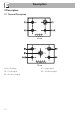
2.2 Symbols 2.3 Available accessories Cooking zones Burner wrench (for installer only) EN Use Front left Rear left Central Rear right Front right Centre left Burner knobs For removing and replacing the hob burners. Useful for lighting and adjusting the hob burners. Press and turn the knobs anticlockwise to the value to light the relative burners. Turn the knobs to the zone between the maximum and minimum setting to adjust the flame. Return the knobs to the position to turn off the burners.
Use 3 Use 3.2 First use 3.1 Instructions Improper use Danger of burns • Make sure that the flame-spreader crowns are correctly positioned in their housings with their respective burner caps. • Oils and fat could catch fire if overheated. Be very careful. • Do not leave the appliance unattended during cooking operations where fats or oils could be released. • Do not spray any spray products near the appliance. • Do not touch the appliance's heating elements when it is running.
Cleaning and maintenance Correct positioning of the flamespreader crowns and burner caps flame far enough to ensure that the liquid does not boil over. EN Correct positioning of the grids The grids over the burners must be positioned in parallel to the control panel, not perpendicular. Cookware diameters: • Auxiliary: 7 - 18 cm. • Semi-rapid: 10 - 24 cm. • Reduced rapid: 18 - 24 cm. • Medium rapid: 20 - 26 cm. • Large rapid: 20 - 26 cm.
Cleaning and maintenance 4 Cleaning and maintenance 4.2 Cleaning the appliance 4.1 Instructions To keep the surfaces in good condition, they should be cleaned regularly after use. Let them cool first. Improper use Risk of damage to surfaces • Do not use steam jets for cleaning the appliance. • Do not use cleaning products containing chlorine, ammonia or bleach on steel parts or parts with metallic finishes on the surface (e.g. anodizing, nickel- or chromium-plating).
Cooking hob grids Igniters and thermocouples Remove the grids and clean them with lukewarm water and non-abrasive detergent. Make sure to remove any encrustations. Dry them thoroughly and return them to the hob. For correct operation the igniters and thermocouples must always be perfectly clean. Check them frequently and clean them with a damp cloth if necessary. Remove any dry residues with a wooden toothpick or a needle.
Installation 5 Installation 5.1 Clearances above and around domestic appliances This appliance must be installed by an authorised person in accordance with this instruction manual, AS/NZS 5601.1 – Gas installations (installation and pipe sizing), local gas fitting regulations, local electrical regulations, Building Code of Australia and any other government authority. Requirements 1.
3. Additional requirements for Freestanding and Elevated Cooking Appliaces – (Measurements D & E) Where D, the distance from the periphery of the nearest burner to a horizontal combustible surface is less than 200 mm, then E shall be 10 mm or more, or the horizontal surface shall be above the trivet. See insets above. 5.2 Safety instructions Notes Veneers, adhesives or plastic coatings on adjacent furniture should be temperatureresistant (>90°C), otherwise they might warp over time. 1.
Installation 5.3 Section cut from the work surface The following operation requires building and/or carpentry work and must therefore be carried out by a competent tradesman. Installation can be carried out on various materials such as masonry, metal, solid wood or plastic laminated wood as long as they are heat resistant (>90°C). 5.
Over empty kitchen unit or drawers Hob seal If there are other pieces of furniture (lateral walls, drawers, etc.), dishwashers or fridges under the hob, a double-layer wooden base must be installed at least 10 mm from the bottom of the hob to avoid any accidental contact. It must only be possible to remove the double-layer base using suitable equipment.
Installation 5.6 Gas connection Gas leak Danger of explosion • After carrying out any operation, check that the tightening torque of gas connections is between 10 Nm and 15 Nm. • If required, use a pressure regulator that complies with current regulations. • At the end of the installation, check for any leaks with a soapy solution, never with a flame.
Installation Connection to liquid gas EN Before the appliance is operated make certain all relevant parts are placed in the correct position. On completion of the installation, the installer MUST check for gas leaks and test each burner individually for the correct flame. Once all burners have been tested individually, turn all burners on together.
Installation Extraction of the combustion products The combustion products may be extracted by means of hoods connected to a natural draught chimney whose efficiency is certain or via forced extraction. An efficient extraction system requires precision planning by a specialist qualified in this area and must comply with the positions and distances indicated by the applicable standards. When the job is complete, the installer must issue a certificate of conformity. 5.
Installation 5. Remove the top. EN 3. Pull the knobs upwards to remove them. 4. Unscrew the burner rings using the supplied wrench.
Installation Burner and nozzle characteristics table 1 ULPG 2.75 kPa AUX SR RR R1 R2 Nominal gas consumption (MJ/h) Injector (1/100 mm) Primary air (mm) 4.1 54 4 6.0 67 2 9.4 82 2 14.5 100 10 10.8 85 3 2 NG 1.0 kPA AUX SR RR R1 R2 Nominal gas consumption (MJ/h) Injector (1/100 mm) Primary air (mm) 4.7 98 4 6.1 110 3 9.4 135 2 14.5 170 6 10.8 145 5 Replacing nozzles 1. Unscrew screw A and push air regulator B as far as it will go. 2.
Adjusting the minimum setting for natural gas Light the burner and turn it to the minimum position. Extract the gas tap knob and turn the adjustment screw next to the tap rod (depending on the model) until the correct minimum flame is achieved. Refit the knob and verify that the burner flame is stable. Turn the knob rapidly from the maximum to the minimum setting: the flame should not go out. Repeat the operation on all gas taps.
Installation Power voltage Danger of electrocution • Have the electrical connection performed by authorised technical personnel. • Use personal protective equipment. • The appliance must be connected to earth in compliance with electrical system safety standards. • Disconnect the main power supply. • Do not pull the cable to remove the plug. • Use cables withstanding a temperature of at least 90°C. • The tightening torque of the screws of the terminal supply wires must be 1.5 - 2 Nm.