Contents 1.1 1.2 1.3 1.4 1.5 1.6 1.7 General safety instructions Appliance purpose Manufacturer’s liability This user manual Identification plate Disposal How to read the user manual 2 Description 2.1 General description 2.2 Symbols 2.3 Available accessories 3 Use 58 58 61 62 62 62 62 63 64 64 65 67 68 3.1 Instructions 3.2 Precautions 3.3 First use 3.4 Using the gas burners 3.5 Using the induction hot plates 3.6 Special functions 3.7 Additional functions 3.8 User menu 3.9 Error codes 3.
Instructions 1 Instructions 1.1 General safety instructions Risk of personal injury • During use the appliance and its accessible parts become very hot. Never touch the heating elements during use. • Never try to put out a fire or flames with water: Turn off the appliance and smother the flames with a fire blanket or other appropriate cover.
Instructions replace it. Risk of damaging the appliance • Do not use abrasive or corrosive detergents (e.g. scouring powders, stain removers and metallic sponges) on glass parts. • Use wooden or plastic utensils. • Do not sit on the appliance. • Do not use steam jets to clean the appliance. • Do not obstruct ventilation openings and heat dispersal slots. • Never leave the appliance unattended during cooking operations where fats or oils could be released, as these could then heat up and catch fire.
Instructions • Take care not to spill acid substances such as lemon juice or vinegar on the hob. • Do not put empty pans or frying pans on switched on cooking zones. • Do not use steam jets to clean the appliance. • Do not use rough or abrasive materials or sharp metal scrapers. • Do not use cleaning products containing chlorine, ammonia or bleach on parts made of steel or that have metallic surface finishes (e.g. anodizing, nickel- or chromium-plating). • Do not use abrasive or corrosive detergents (e.g.
• At the end of the installation, check for any leaks with a soapy solution, never with a flame. • Have the electrical connection performed by authorised technical personnel. • The appliance must be connected to earth in compliance with electrical system safety standards. • Use cables withstanding a temperature of at least 90°C. • The tightening torque of the screws of the terminal supply wires must be 1.5 - 2 Nm.
Instructions 1.3 Manufacturer’s liability The manufacturer declines all liability for damage to persons or property caused by: • Use of the appliance other than that specified • Failure to comply with the instructions in the user manual • Tampering with any part of the appliance • The use of non-original spare parts. 1.4 This user manual This user manual is an integral part of the appliance and must therefore be kept in its entirety and within the user’s reach for the whole working life of the appliance.
Instructions Plastic packaging Danger of suffocation • Do not leave the packaging or any part of it unattended. • Do not let children play with the plastic bags. 1.7 How to read the user manual This user manual uses the following reading conventions: Instructions General information on this user manual, on safety and final disposal.
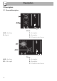
Description 2 Description 2.
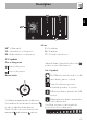
EN Description 90 cm UR* = Ultra rapid SX = Left induction cooking zone DX = Right induction cooking zone F = Front plate R = Rear plate C = General controls zone 2.2 Symbols Gas cooking zone Rear cooking zone adjust the flame. Return the knobs to the position to turn off the burners. Front cooking zone List of symbols Burner knobs On/Off button: turns the hob on or off. Pause button: pauses cooking. Controls lock button: prevents accidental operation of controls.
Description Maximum absorbed power table (Watt) Dimensions H x L (mm) Level 9 Booster Double Booster Single zone 180 x 240 2100 W 2500 W 3000 W Multizone 360 x 240 3000 W 3700 W - * power levels are approximate and may vary according to the pan used or the settings made. Advantages of induction cooking The appliance is equipped with an induction generator for each cooking zone.
Description 2.3 Available accessories EN Wok support (on some models only) Useful when using a wok. The accessories intended to come into contact with food are made of materials that comply with the provisions of current legislation. Original supplied and optional accessories can be requested to Authorised Assistance Centres. Use only original accessories supplied by the manufacturer.
Use 3 Use 3.1 Instructions Improper use Danger of burns • Make sure that the flame-spreader crowns are correctly positioned in their housings with their respective burner caps. • Do not leave the appliance unattended during cooking operations where fats or oils could be released. • Oils and fats could catch fire if overheated. Be very careful. • Protect your hands by wearing heatproof gloves during use.
Use A gas leak can cause an explosion. If you smell gas or there are faults in the gas system: • Immediately turn off the gas supply or close the valve on the gas cylinder. • Extinguish all naked flames and cigarettes. • Do not turn on power switches or appliances and do not remove plugs from power sockets. Do not use phones or mobile phones inside the building. • Open the window in order to ventilate the room. • Call customer assistance services or your gas supplier.
Use Correct positioning of the flamespreader crowns and burner caps Before lighting the hob burners, make sure that the flame-spreader crowns are correctly positioned in their housings with their respective burner caps. Make sure that the holes in the burners are aligned with the igniters and thermocouples. Also ensure that the flame-spreader crowns are correctly engaged in the burner holes.
Trivets and reduction pan supports 3.5 Using the induction hot plates The trivet/support must be rested on the hob pan supports. Make sure they are properly positioned. All the appliance’s control and monitoring devices are located together on the front panel. The induction hob is controlled by means of the Touch control sensor buttons. Lightly touch a symbol on the glass ceramic surface. A beep will sound to confirm every effective touch.
Use Minimum cookware diameter Make sure that the minimum diameter of the pans are those indicated in the following table, for both configurations. Configu- Minimum Ø Maximum Ø (cm) (cm) ration Single plate 11 18 Multizone* 18 22 *Values for one pan, if two pans are used refer to the values for a single hot plate configuration. Bear in mind the following: • Do not allow the pans to extend beyond the vertical lines. • Do not cover the control panel.
Use Limiting the cooking duration The hob has an automatic device which limits the duration of use. If the cooking zone settings are not changed, the maximum duration of operation for each zone depends on the power level selected. When the device for limiting the duration of use is activated, the cooking zone turns off, a short alert sounds and, if the zone is hot, the symbol appears on the display.
Use Power levels The power in the cooking zone can be adjusted to various levels. The table shows the levels suitable for various types of cooking.
Use to or activate the Booster function (see “Booster Function”). Quick selection This function allows you to quickly set the cooking zones to the required power. After switching on the hob and having selected a cooking zone: 1. Place a finger on the scroll bar at approximately the required power level. The display of the zone being used will indicate the selected power level. Switching off the cooking zone 1.
Use After switching on the hob and having selected a cooking zone: 1. Place a finger on the left-hand side of the scroll bar. The Booster function can be activated quickly. • After switching on the hob, place your finger at the far right of the scroll bar of the cooking zone you wish to use. The display of the cooking zone used will turn on: the power value indicated is . 2. Move your finger all the way to the right of the scroll bar to select the Booster function.
Use This function can be used to operate two cooking zones (front and when using pans like fish kettles or rectangular pans. The same parameters are set on both cooking zones. It is only possible to activate the Multizone function between cooking zones that are vertically connected (F and R). EN Multizone function After switching on the hob: 1. Place a finger simultaneously on the buttons of two cooking zones one above the other.
Use Example of incorrect pan position To deactivate the Multizone function: Simultaneously press the buttons of the cooking zones on which the Multizone function is active. The symbol disappears and the two zones can be regulated separately. Cooking guidelines The table below shows the power values which can be set, together with the corresponding type of food. Settings may vary depending on the amount of food and consumer taste.
3.6 Special functions To deactivate the Pause function: Warning Function 1. Hold down the button . The pause symbol, which has just been pressed, starts to flash. 2. Press any button apart from the Pause button 3. The pause function has now been deactivated and the previously set functions are restored. This function allows you to keep cooked food warm or to keep water on the boil. To activate the Warming function, first turn on the hob, then: 1. Select a cooking zone. 2. Press the function.
Use The symbol appears on the front zone display and the symbol appears on the rear zone display. The scroll bar will be set automatically to level 8. (preheating stage) After two minutes of operation, the power will be reduced to level 6. Press the button and use the scroll bar to modify the power level at any time. Controls lock This function allows you to disable all the buttons of the appliance. This is useful when cleaning the appliance and to prevent functions being activated by mistake.
Use • The first digit on the left is used to select the hours, the middle one to set the tens of minutes and the one on the right the minutes. After switching on the appliance, touch the timer setting area within 3 seconds, otherwise it will deactivate and the appliance will have to be restarted. 3. After 10 seconds, the timer will start the countdown. 4. When the time elapses, a series of beeps will sound. Press any button to deactivate them. A maximum of 9 hours and 59 minutes can be set.
Use 3. Use the + and - buttons to select the required time. 3. Use the + and - buttons to modify or reset the timer. 4. After 10 seconds, the timer will start the new countdown or will be deactivated. An independent timer can be set during timed cooking. 4. Timed cooking will start a few seconds after the last selection. At the end of the set time, a buzzer tells the user that the Minute minder has finished. 5. Press any button to deactivate the buzzer. A maximum of 9 hours and 59 minutes can be set.
Use Description U0 Maximum total power (kW) U1 Option not selectable U2 Button volume U3 Buzzer volume U4 Display brightness U5 Timer animation U6 Automatic pan detection U7 Timer alarm duration Accessing the user menu 1. If the hob is off, switch it on using the On/Off button 2. Press . again within 3 seconds to switch it off; the Press and hold button starts to flash. . 3.
Use Table of power draws Model Minimum power (kW) Maximum power (kW) 90 cm 2.4 7.4 65 cm - 75 cm 2.4 3.7 • Press the symbol to go back to selecting the options. • Press the segments of the scroll bar to select an option. Each segment of the scroll bar corresponds to an item in the user menu, except for the second segment from the left (U1), which is deactivated. Option U2 modifies the volume of the button sounds; 4 sound levels can be selected using the scroll bar.
Use Exiting the user menu There are two ways to exit from the user menu: 1. Press the button. Any modifications will be discarded and the hob will be switched off. Or 3.10 Practical advice • For better burner efficiency and to minimise gas consumption, use pans with lids and of suitable size for the burner, so that the flames do not reach up the sides of the pan. Once the contents come to the boil, turn down the flame far enough to ensure that the liquid does not boil over.
Use • The diameter of the base of the pan must not exceed the width of the silk-screened cooking zone. • Pans must not be placed outside the perimeter of the hob or above the front control panel. • When buying a pan, check whether the diameter indicated is that of the base or the top of the pan, as the top is almost always larger than the base. • When preparing dishes with long cooking times, you can save time and energy by using a pressure cooker, which also helps to retain vitamins contained in the food.
4 Cleaning and maintenance 4.2 Cleaning the appliance 4.1 Instructions To keep the surfaces in good condition, they should be cleaned regularly after use. Let them cool first. Improper use Risk of damage to surfaces • Do not use steam jets to clean the appliance. • Do not use cleaning products containing chlorine, ammonia or bleach on parts made of steel or that have metallic surface finishes (e.g. anodizing, nickelor chromium-plating). • Do not use abrasive or corrosive detergents (e.g.
Cleaning and maintenance Food stains or residues Do not use steel sponges and sharp scrapers as they will damage the surface. Use normal, non-abrasive products and a wooden or plastic tool, if necessary. Rinse thoroughly and dry with a soft cloth or a microfibre cloth. Do not allow residues of sugary foods (such as jam) to set inside the oven. If left to set for too long, they might damage the enamel lining of the oven.
Flame-spreader crowns and burner caps 4.3 What to do if... For easier cleaning, the flame-spreader crowns and the burner caps can be removed. Wash them in hot water and nonabrasive detergent. Carefully remove any encrustation, then wait until they are perfectly dry. Replace the flame-spreader crowns, making sure that they are correctly positioned in their housings with their respective burner caps. The hob does not work: • Make sure that the hob is connected and that the main switch is turned on.
Cleaning and maintenance 5 Installation 5.1 Safety instructions Appliance dimensions (mm) Position of gas and electrical connections. (seen from below) Heat production during appliance operation Risk of fire • Check that the carcase material is heat resistant. • Check that the carcase has the required openings. Veneers, adhesives or plastic coatings on adjacent furniture should be temperatureresistant (>90°C), otherwise they might warp over time.
Installation The following operation requires building and/or carpentry work and must therefore be carried out by a competent tradesman. Installation can be carried out on various materials such as masonry, metal, solid wood or plastic laminated wood as long as they are heat resistant (>90°C). Flush mounted installation Make a hole in the countertop of the unit according to the dimensions shown in the figure (mm). L 650 750 900 A min. 200 B min. 460 C min. 750 D 40-60 E min.
Installation Flush mounting dimensions (mm) Semi-flush mounting dimensions (mm) 1 = Gas connection 2 = Electrical connection 1 = Gas connection 2 = Electrical connection A 654 754 904 B 93 66 75 C 35 35 35 D 69 69 70 E 85 53 112 F 46 16 29 Semi-flush installation Make a hole in the countertop of the unit according to the dimensions shown in the figure (mm).
Installation It must only be possible to remove the double-layer base using suitable equipment. EN If installed above an oven, a space must be left between the bottom of the hob and the top of the appliance installed below. 150 x 150 (mm) required for gas connection opens on bottom opens on bottom opens on bottom and on rear If installed on top of an oven, the latter must be equipped with a cooling fan.
Installation Spring clips To ensure the hob is fixed and centred as accurately as possible, the clips provided must be positioned as described below: 1. Fit the clips by gently pressing them horizontally into the appropriate space. 75 cm 2. Then turn them upwards to fix them in place. 90 cm Ventilation Position of slot for clips (seen from below) 65 cm 94 The illustrations below show two examples of installation suitable for proper ventilation and one example of incorrect installation to be avoided.
Installation Connection to the gas mains can be made using a rigid copper pipe or a continuous wall steel hose in compliance with the provisions established by the applicable standard. For supplying it with other types of gas, see chapter “5.5 Adaptation to different types of gas”. The gas inlet connection is threaded ½” external gas (ISO 228-1). Connection with a steel hose with conical fitting 5.
Installation Connection with a steel hose Room ventilation Make the connection to the gas mains using a continuous wall steel hose whose specifications comply with the applicable standard. Carefully screw the connector 3 to the gas connector 1 of the appliance, placing the seal 2 between them. The appliance should be installed in rooms that have a permanent air supply in accordance with the standards in force.
Installation 5.5 Adaptation to different types of gas If other types of gas are to be used, the nozzles must be replaced and the primary air must be adjusted. The top of the hob has to be removed in order to replace the nozzles and adjust the burners. In order to be able to replace the nozzles, the appliance must be removed from the built-in unit. Removing the hob top 1. Pull the knobs and the knob bezels (where present) upwards to remove them.
Installation 2. Remove the pan support grids from the hob. 4. Remove the screws fastening the hob and the plates corresponding to each burner zone. 3. Remove the flame-spreader crowns and relative burner caps. Where the UR burner is present, the nut that fixes the thermocouple to the hob top must be unscrewed (CH8). Under the plates, there may be a number of seals, together with the igniter and thermocouple. Pay attention.
Installation 5. Unscrew the 6 screws that hold the glass hob top to the casing (see the figures below for their location). 6. Remove the glass hob top. EN (seen from below) Replacing the nozzles 65 cm 75 cm 1. Unscrew screw A and push air regulator B as far as it will go. 2. Use a spanner to remove the nozzles C and install the new ones for the required gas supply, following the indications given in the relevant table (see “Gas types and Countries”).
Installation 3. Adjust the air flow by moving the air regulator B to obtain the distance D given in the corresponding table (see “Gas types and Countries”). 4. After adjusting each burner, reassemble the appliance correctly. Adjusting the minimum setting for natural or town gas 1. Light the burner and turn it to the minimum position. 2. Extract the gas cock knob and turn the adjustment screw next to the gas cock spindle (depending on the model) until the correct minimum flame is achieved. 3.
Installation Re-assembling the hob top EN Once the nozzles have been replaced, reassemble the glass hob top as follows: 1. With reference to the gas burners, replace the glass hob top on the casing. 2. For each burner, reposition the seals on the igniter and thermocouple. 3. Reposition the plates on the corresponding burners and secure with the 3 screws (for each burner) that had previously been removed. 4. If present, tighten the nut on the UR burner igniter. 5.
Installation Gas types and Countries Gas types 1 Natural Gas G20 G20 20 mbar G20/25 20/25 mbar 2 Natural Gas G20 G20 25 mbar 3 Natural Gas G25 G25 25 mbar G25.3 25 mbar 4 Natural Gas G25.1 G25.1 25 mbar 5 Natural Gas G25 G25 20 mbar 6 Natural Gas G2.350 G2.
Installation 1 Natural Gas G20 - 20 mbar Rated heating capacity (kW) Nozzle diameter (1/100 mm) Reduced flow rate (W) Primary air (mm) 2 Natural Gas G20 - 25 mbar Rated heating capacity (kW) Nozzle diameter (1/100 mm) Reduced flow rate (W) Primary air (mm) 3 Natural gas G25/G25.3 - 25 mbar Rated heating capacity (kW) Nozzle diameter (1/100 mm) Reduced flow rate (W) Primary air (mm) 4 Natural Gas G25.
Installation 7 LPG G30/31 - 30/37 mbar AUX R Rated heating capacity (kW) 1.0 3.1 Nozzle diameter (1/100 mm) 48 85 Reduced flow rate (W) 400 1100 Primary air (mm) 1.5 2 Rated flow rate G30 (g/h) 73 225 Rated flow rate G31 (g/h) 71 221 8 LPG G30/31 - 37 mbar AUX R Rated heating capacity (kW) 1.1 3.1 Nozzle diameter (1/100 mm) 48 80 Reduced flow rate (W) 450 1100 Primary air (mm) 1 1.1 Rated flow rate G30 (g/h) 80 225 Rated flow rate G31 (g/h) 79 221 9 LPG G30/31 - 50 mbar AUX R Rated heating capacity (kW) 1.
5.6 Electrical connection Power voltage Danger of electrocution • Have the electrical connection performed by authorised technical personnel. • Use personal protective equipment. • The appliance must be connected to earth in compliance with electrical system safety standards. • Disconnect the mains power supply. • Do not pull the cable to unplug the appliance. • Use cables withstanding a temperature of at least 90°C. • The tightening torque of the screws of the terminal supply wires must be 1.5 2 Nm.
Installation The diagram below illustrates the power supply terminal from below, with no cables connected. Terminals 4 and 5 must be connected at all times. Testing At the end of installation, carry out a brief inspection test. If the hob fails to operate, after checking that you have carried out the instructions correctly, unplug the appliance and contact Technical Support. 5.
EN Installation 107