
User manual


Instructions for the installer
23
2)
3)
4)
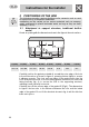
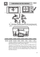
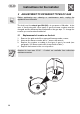
2.2 Attachment to support structure, flush-mounting model
Create an opening with the dimensions shown in the figure in the wor
k
surface.
A (mm) B (mm) C (mm) D (mm) E (mm) L (mm) X (mm) Y (mm)
min 110 min 460 min 750 20÷40 min 50 870 482 847
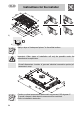
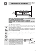
This type of appliance also requires a cut 3 mm deep in the work-top with
the dimensions shown in figure 4 (detail A, figure 2).
Before positioning the hob, position the adhesive sponge material “E”
supplied over the milled surface (fig. 2). Now place the hob on the cut in
the work-top and use the screws and fixing brackets (sequence shown in
Fig. 3) to secure the hob to the supporting structure, adjusting it until
perfectly horizontal. Do not fit the brackets shown in fig. 3 until the hob
has been set in place.