
User manual


Instructions for the installer
22
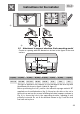
2 POSITIONING OF THE HOB
The following operation requires building and/or carpentry work so must
be carried out by a competent tradesman.
Installation can be carried out on various materials such as masonry,
metal, solid wood or plastic laminated wood, as long as they are heat-
resistant
(
T 90°C
)
.
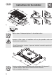
2.1 Attachment to support structure, traditional built-in
model
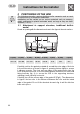
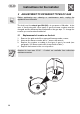
Create an opening with the dimensions shown in the figure in the work surface.
A (mm) B (mm) C (mm) D (mm) E (mm) L (mm) X (mm) Y (mm)
min 110 min 460 min 750 20÷50 min 50 870 482 847
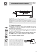
Carefully position the gasket provided all around the outer edge of the hole
in the work surface as shown in figure 2, pressing it down lightly to ensure
it adheres properly. The front and rear sides of the gasket must skim the
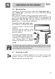
hole. Now place the hob on the insulating gasket and use the screws and
fixing brackets (fig. 4) to secure the hob to the supporting structure,
adjusting it until perfectly horizontal.
Carefully trim off the excess edge of the gasket C (Fig.3). The dimensions
in figure 2 below refer to the distance between the hole and the inside
edge of the gasket. Do not fit the brackets shown in fig. 4 until the hob has
been set in place.