Contents 1 INSTRUCTIONS FOR SAFE AND PROPER USE _______________ 20 2 POSITIONING OF THE HOB _______________________________ 22 3 ADJUSTMENT TO DIFFERENT TYPES OF GAS _______________ 28 4 FINAL OPERATIONS _____________________________________ 30 5 USING THE HOB ________________________________________ 31 6 CLEANING AND MAINTENANCE ___________________________ 33 THESE INSTRUCTIONS ARE VALID ONLY FOR END USER COUNTRIES WHOSE IDENTIFICATION SYMBOLS APPEAR ON THE COVER OF THIS MANUAL.
Introduction 1 INSTRUCTIONS FOR SAFE AND PROPER USE THIS MANUAL IS AN INTEGRAL PART OF THE APPLIANCE AND THEREFORE MUST BE KEPT IN ITS ENTIRETY AND IN AN ACCESSIBLE PLACE FOR THE WHOLE WORKING LIFE OF THE HOB. WE ADVISE READING THIS MANUAL AND ALL THE INSTRUCTIONS THEREIN BEFORE USING THE HOB. ALSO KEEP THE SERIES OF NOZZLES SUPPLIED. INSTALLATION MUST BE CARRIED OUT BY QUALIFIED PERSONNEL IN ACCORDANCE WITH THE REGULATIONS IN FORCE.
Introduction THE APPLIANCE DATA PLATE, WITH TECHNICAL DATA, REGISTRATION NUMBER AND BRAND NAME, IS POSITIONED AT A VISIBLE POINT UNDER THE SAFETY COVER. THE DATA PLATE ON THE PROTECTIVE COVER MUST NEVER BE REMOVED. DO NOT PUT PANS WITHOUT PERFECTLY SMOOTH AND FLAT BOTTOMS ON THE HOB PANSTAND GRIDS. DO NOT USE COOKING RECEPTACLES THAT EXTEND BEYOND THE OUTSIDE PERIMETER OF THE HOB. THE APPLIANCE IS DESIGNED FOR USE BY ADULTS. DO NOT ALLOW CHILDREN TO GO NEAR OR PLAY WITH IT.
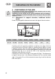
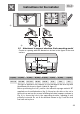
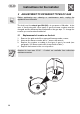
Instructions for the installer 2 POSITIONING OF THE HOB The following operation requires building and/or carpentry work so must be carried out by a competent tradesman. Installation can be carried out on various materials such as masonry, metal, solid wood or plastic laminated wood, as long as they are heatresistant (T 90°C). 2.1 Attachment to support structure, traditional built-in model Create an opening with the dimensions shown in the figure in the work surface.
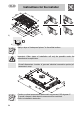
Instructions for the installer 2) 3) 4) 2.2 Attachment to support structure, flush-mounting model Create an opening with the dimensions shown in the figure in the work surface. A (mm) B (mm) C (mm) D (mm) E (mm) L (mm) X (mm) Y (mm) min 110 min 460 min 750 20÷40 min 50 870 482 847 This type of appliance also requires a cut 3 mm deep in the work-top with the dimensions shown in figure 4 (detail A, figure 2).
Instructions for the installer 3) 3 2) A 4) Apply a layer of “waterproof primer” to the milled surface. Important: Other types of installation will only be possible under the manufacturer's supervision. Overall dimensions: location of gas and electrical connection points (all measures in mm). Caution: surface temperature underneath may exceed 125 degrees C. To avoid a hazard, under-bench access must be restricted.
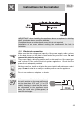
Instructions for the installer IMPORTANT: when installing the appliance above a cupboard, a dividing shelf, as shown above, must be installed. If installed above an under-bench oven, this is not required. Installation of an oven without cooking fan underneath the hob is forbidden. 2.3 Electrical connection Make sure that the voltage and capacity of the power supply cable conform to the data shown on the plate located under the protective cover. Do not remove this plate for any reason.
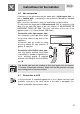
Instructions for the installer Use only H05V2V2-F cable or similar which has a maximum temperature of 90°C. Any replacement needed should be carried out by a specialised technician who should make the mains connections according to the following diagram. L = brown N = blue = yellow-green The manufacturer declines all liability for injury to persons or animals and for damage to property resulting from non-observance of the above prescriptions or from tampering with any part of the appliance. 2.
Instructions for the installer 2.6 Gas connection Connection to the gas mains may be made with a rigid copper pipe or with a flexible pipe conforming to the provisions defined by standard regulations in force. After connection operations, check for leaks using a soapy solution. The hob has been inspected for G20 natural gas (2H) at a pressure of 20 mbar. For use with other types of gas, see chapter “3. ADJUSTMENT TO DIFFERENT TYPES OF GAS.
Instructions for the installer 3 ADJUSTMENT TO DIFFERENT TYPES OF GAS Before performing any cleaning or maintenance work, unplug the appliance from the mains. The hob is set for natural gas G20 (2H) at a pressure of 20 mbar. In the case of functioning with other types of gas the burner nozzles must be changed and the minimum flame adjusted on the gas taps. To change the nozzles, proceed as described below. 3.1 1. 2. 3. 4.
Instructions for the installer 3.2 Burner and nozzle characteristics table Rated heating capacity (kW) Burner LPG – G30/G31 30/37 mbar Nozzle diameter 1/100 mm By-pass mm 1/100 Reduced flow rate (W) Flow rate g/h G30 Flow rate g/h G31 Auxiliary (1) 1.05 50 30 (*) 28/30 (**) 400 76 75 Semi rapid (2) 1.75 65 30 (*) 32/33 (**) 500 130 128 Rapid (3) 2.3 75 45 (*) 42/45 (**) 800 166 164 Ultra rapid (4) 3.
Instructions for the installer 4 FINAL OPERATIONS After carrying out the above adjustments, remount in reverse order to the instructions given in paragraph “3.1 Replacement of nozzles on the hob”. After adjustment to a different kind of gas from the one for which the appliance has been tested, replace the plate inside the storage compartment with one corresponding to the new kind of gas. The label is available from your nearest Authorised Assistance Centre. 4.
Instructions for the user 5 USING THE HOB 5.1 Ignition of the burners Before turning on the burners, make sure that the flame-spreader crowns and respective caps are properly fitted in their housings. Ensure the flame-spreader holes A are aligned with the ignition plugs and the thermocouples. To prevent damage to the work top, the hob comes complete with a raised pan stand H. This must be placed under pans with a diameter bigger than those indicated in the table in paragraph "5.3 Pan diameters".
Instructions for the user 5.2 Practical advice for using the burners For better use of the burners and lower gas consumption, use covered cooking receptacles that have a flat, smooth bottom and are proportional in size to the burner to prevent the flame from licking the sides (see paragraph “5.3 Pan diameters”). When water reaches boiling point, lower the flame so that it does not boil over.
Instructions for the user 6 CLEANING AND MAINTENANCE Before any intervention, disconnect the appliance from the mains. Never use a steam jet to clean the appliance. 6.1 Cleaning the stainless steel To keep stainless steel in good condition it should be cleaned regularly after use. Let it cool first. 6.1.1 Routine daily cleaning To clean and preserve the stainless steel surfaces, always use only specific products that do not contain abrasives or chlorine-based acids.
Instructions for the user the figure below for guidance.