
Instruction manual


Installation
58
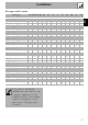
Burner and nozzle characteristics tables
1 Natural gas G20 - 20 mbar AUX RR UR3
Rated heating capacity (kW)
1.05 2.50 3.90
Nozzle diameter (1/100 mm)
72 108 135
Reduced flow rate (W)
400 800 1600
Pre-chamber (printed on nozzle)
XYK
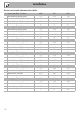
2 Natural gas G20 - 25 mbar AUX RR UR3
Rated heating capacity (kW)
1.05 2.50 3.90
Nozzle diameter (1/100 mm)
72 100 126
Reduced flow rate (W)
400 800 1600
Pre-chamber (printed on nozzle)
XF2K
3 Natural gas G25.1 – 25 mbar AUX RR UR3
Rated heating capacity (kW)
1.05 2.50 3.90
Nozzle diameter (1/100 mm)
77 115 148
Reduced flow rate (W)
400 800 1600
Pre-chamber (printed on nozzle)
F1 F3 F3
4 Natural Gas G25 – 20 mbar AUX RR UR3
Rated heating capacity (kW)
1.05 2.50 3.90
Nozzle diameter (1/100 mm)
77 115 148
Reduced flow rate (W)
400 800 1600
Pre-chamber (printed on nozzle)
F1 F3 F3
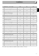
5 Natural Gas G27 – 20 mbar AUX RR UR3
Rated heating capacity (kW)
1.05 2.60 3.70
Nozzle diameter (1/100 mm)
77 134 152
Reduced flow rate (W)
400 800 1600
Pre-chamber (printed on nozzle)
F1 Z F3
6 Natural gas G2.350 – 13 mbar AUX RR UR3
Rated heating capacity (kW)
1.00 2.50 3.80
Nozzle diameter (1/100 mm)
94 152 200
Reduced flow rate (W)
400 800 1600
Pre-chamber (printed on nozzle)
YF3H2