Table of contents 1.1 1.2 1.3 1.4 1.5 1.6 1.7 General safety instructions Manufacturer liability Appliance purpose Identification plate This user manual Disposal How to read the user manual 2 Description 2.1 General Description 2.2 Symbols 2.3 Available accessories 3 Use 34 34 37 38 38 38 38 39 40 40 40 41 42 3.1 Instructions 3.2 First use 3.3 Using the hob 42 42 42 4 Cleaning and maintenance 45 4.1 Instructions 4.2 Cleaning the appliance 45 45 5 Installation 5.1 5.2 5.3 5.4 5.5 5.6 5.
Instructions 1 Instructions 1.1 General safety instructions Risk of personal injury • During use the appliance and its accessible parts become very hot. Never touch the heating elements during use. • Never try to put out a fire or flames with water: turn off the appliance and smother the flames with a fire blanket or other appropriate cover.
• Do not use aerosols in the vicinity of this appliance whilst it is in use. • Switch off the appliance after use. • Do not modify this appliance. • Do not try to repair the appliance yourself or without the intervention of a qualified technician. • Do not pull the cable to remove the plug. • If the power supply cable is damaged, contact technical support immediately and they will replace it. Risk of damaging the appliance • Do not sit on the appliance. • Do not use steam jets to clean the appliance.
Instructions • Do not wash the removable components such as the hob grids, flame-spreader crowns and burner caps in a dishwasher. Installation • This appliance must not be installed in a boat or caravan. • This appliance must not be installed on a pedestal. • Position the appliance into the cabinet cut-out with the help of a second person. • To prevent any possible overheating, the appliance should not be installed behind a decoration door or a panel.
Instructions For this appliance • Do not obstruct ventilation openings and heat dispersal slots. • Do not insert pointed metal objects (cutlery or utensils) into the slots in the appliance. • Do not use the appliance to heat rooms for any reason. • The appliance is not designed to operate with external timers or with remote-control systems. 1.2 Manufacturer liability EN • The adjustment conditions for this appliance are shown on the gas setting label.
Instructions 1.3 Appliance purpose This appliance is intended for cooking food in the home environment. Every other use is considered inappropriate. 1.4 Identification plate The identification plate bears the technical data, serial number and brand name of the appliance. Do not remove the identification plate for any reason. 1.
Instructions Plastic packaging Danger of suffocation • Do not leave the packaging or any part of it unattended. • Do not let children play with the plastic bags. 1.7 How to read the user manual This user manual uses the following reading conventions: Instructions General information on this user manual, on safety and final disposal. Description EN Our appliances are packaged in non-polluting and recyclable materials. • Deliver the packing materials to the appropriate recycling centre.
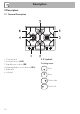
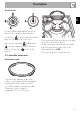
Description 2 Description 2.1 General Description 1. Control panel 2. Auxiliary Burner (AUX) 3. Rapid burner reduced(RR) 4. Ultra-rapid triple crown burner (UR3) 5. Right grid 6. Left grid 2.
Description EN Burner knobs Used for lighting and adjusting the hob burners. Press and turn the knobs anticlockwise to in order to light the relative burners. Turn the knobs to the zone between the maximum and minimum setting to adjust the flame. Return the knobs to the position to turn off the burners. The ring must be placed under the hob grid as shown in the picture above. In any case, pans with a diameter greater than 28 cm must be used solely on the Ultra-rapid burner (UR3).
Use 3 Use 3.2 First use 3.1 Instructions Improper use Danger of burns • Make sure that the flame-spreader crowns are correctly positioned in their seats with their respective burner caps. • Oils and fats could catch fire if overheated. Be very careful. • Do not leave the appliance unattended during cooking operations where fats or oils could be released. • Do not spray any spray product near the appliance. • Do not touch the appliance’s heating elements when it is running.
Positioning the pan stands Practical tips for using the hob The pan stands are provided unassembled on the hob. To install the grids correctly, follow the instructions as shown in the figure. For better burner efficiency and to minimise gas consumption, use pans with lids and of suitable size for the burner, so that the flames do not reach up the sides of the pan. Once the contents come to the boil, turn down the flame far enough to ensure that the liquid does not boil over.
Use Limitations on griddle use A few precautions are necessary if you wish to use a griddle: • The griddles should not exceed the perimeter of the hob. • Aluminium griddles with Teflon anti-stick coating should be pre-heated for a maximum of 5 minutes in order to avoid damage to the appliance and the Teflon coating. After pre-heating, place the foodstuffs on the griddle to cook them; do not exceed 40 minutes of total use for the griddle.
Cleaning and maintenance 4.1 Instructions Improper use Risk of damage to surfaces • Do not use steam jets to clean the appliance. • Do not use cleaning products containing chlorine, ammonia or bleach on parts made of steel or that have metallic surface finishes (e.g. anodizing, nickelor chromium-plating). • Do not use rough or abrasive materials or sharp metal scrapers. • Do not wash the removable components such as the hob grids, flame-spreader crowns and burner caps in a dishwasher. 4.
Cleaning and maintenance Flame-spreader crowns and burner caps Igniters and thermocouples For easier cleaning, the flame-spreader crowns and the burner caps can be removed. Wash them in hot water and nonabrasive detergent. Carefully remove any encrustation, then wait until they are perfectly dry. Refit the flame-spreader crowns making sure that they are correctly positioned in their housings with their respective burner caps.
Installation 5.2 Positioning in the counter top The following operation requires building and/or carpentry work and must therefore be carried out by a competent tradesman. Installation can be carried out on various materials such as masonry, metal, solid wood or plastic laminated wood as long as they are heat resistant (>90°C). 5.1 Safety instructions Heat production during appliance operation Risk of fire • Make sure that the cabinet material is heat resistant.
Installation To prevent leakage of liquid between the frame of the hob and the work surface, carefully put the insulating seal provided in position before assembly. 1. Refer to the dimensions in the figure, bearing in mind that the front and rear long sides must brush against the hole. 2. Make the seal stick to the edge around the hole cut in the worktop, using a slight pressure; front and rear sides of the seal must brush against the hole. 48 3.
Installation L (mm) X (mm) Y (mm) 620 592 488 L (mm) X (mm) Y (mm) G (mm) H (mm) 620 592 488 621 513 B (mm) C (mm)* D (mm) E (mm) min 150 min 460 min 750 20 - 40 A (mm) min 50 EN Fixing to the flush built-in model support structure Create an opening with the dimensions shown in the figure in the countertop of the piece of furniture. This kind of built-in application needs a milling on the hob top of 3 mm in depth (detail "B" in the picture above).
Installation Overall dimensions: gas and electrical connection location (measurements in mm) After these operations, secure the appliance through the supplied special brackets (A) to get a perfect level, according to the instructions in the picture. View from the bottom A Gas pipe connection B Electrical connection Right view The brackets should be placed only after the hob has been laid on the seal.
Installation 5.3 Mounting The clearance between the hob and the kitchen furniture or other installed appliances must be enough to ensure sufficient ventilation and air discharge. If installed above an oven, a space must be left between the bottom of the hob and the top of the appliance installed below. EN Over built-in oven unit opens on rear Over empty kitchen unit or drawers If there are other pieces of furniture (lateral walls, drawers, etc.
Installation 5.4 Gas connection Gas leak Danger of explosion • After carrying out any operation, check that the tightening torque of gas connections is between 10 Nm and 15 Nm. • If required, use a pressure regulator that complies with current regulations. • At the end of the installation, check for any leaks with a soapy solution, never with a flame. • The hoses should not come into contact with moving parts and should not be crushed in any way.
Installation Room ventilation The appliance should be installed in rooms that have a permanent air supply in accordance with the standards in force. The room where the appliance is installed must have enough air flow for the regular combustion of gas and the necessary air change in the room itself. The air vents, protected by grilles, must be the right size to comply with current regulations and positioned so that no part of them is obstructed, not even partially.
Installation Extraction of the combustion products This appliance is not connected to an exhaust system for combustion products. It must be installed and connected in compliance with the current installation regulations. Special attention should be paid to the relevant requirements as for ventilation. The combustion products may be extracted by means of hoods connected to a natural draught chimney whose efficiency is certain or via forced extraction.
Installation In case of operation with other types of gas, the burner nozzles must be changed and the minimum flame adjusted on the gas taps. 3. Replace the burner nozzles using a 7 mm socket wrench according to the gas to be used (see "Nozzle and burner specification tables"). EN 5.5 Adaptation to different types of gas Changing the nozzles 1. Remove the grids from the hob. 4. Reposition the burners in their respective housings. 2. Remove the flame-spreader crowns and relative burner caps.
Installation Adjusting the minimum setting for natural or town gas 1. Light the burner and turn it to the minimum position. 2. Remove the knobs by pulling them upwards. 5. Turn the knob rapidly from the maximum to the minimum setting: The flame should not go out. Repeat the operation on all gas cocks. Adjusting the minimum setting for LPG Tighten the screw located at the side of the cock rod clockwise all the way.
Installation Gas types and Countries 1 Natural gas G20 G20 20 mbar G20/25 20/25 mbar 2 Natural gas G20 G20 25 mbar 3 Natural gas G25.1 G25.1 25 mbar 4 Natural gas G25 G25 20 mbar 5 Natural gas G27 G27 20 mbar 6 Natural gas G2.350 G2.
Installation Burner and nozzle characteristics tables 1 Natural gas G20 - 20 mbar AUX RR UR3 Rated heating capacity (kW) 1.05 2.50 3.90 Nozzle diameter (1/100 mm) 72 108 135 Reduced flow rate (W) 400 800 1600 Pre-chamber (printed on nozzle) 2 Natural gas G20 - 25 mbar X AUX Y RR K UR3 Rated heating capacity (kW) 3.90 1.05 2.50 Nozzle diameter (1/100 mm) 72 100 126 Reduced flow rate (W) 400 800 1600 Pre-chamber (printed on nozzle) 3 Natural gas G25.
7 LPG G30/31 - 30/37 mbar AUX RR UR3 Rated heating capacity (kW) 3.90 1.05 2.50 Nozzle diameter (1/100 mm) 50 79 100 Reduced flow rate (W) 400 500 1600 Pre-chamber (printed on nozzle) - H8 - Rated flow rate G30 (g/h) 76 182 284 Rated flow rate G31 (g/h) 75 AUX 179 RR 279 UR3 1.10 2.50 4.
Installation 5.6 Electrical connection Power voltage Danger of electrocution • Have the electrical connection performed by authorised technicians. • Use personal protective equipment. • The appliance must be connected to ground in compliance with electrical system safety standards. • Disconnect the mains power supply. • Do not pull the cable to remove the plug. • Use cables withstanding a temperature of at least 90°C. • The tightening torque of the screws of the terminal board leads must be 1.5 - 2 Nm.
Connection with plug and socket 5.7 Instructions for the installer Make sure that the plug and socket are of the same type. Avoid using adapters and shunts as these could cause overheating and a risk of burns. • The plug must be accessible after installation. Do not bend or trap the power cable. • The appliance must be installed according to the installation diagrams. • Do not try to unscrew or force the threaded elbow of the fitting.