Contents 1.1 1.2 1.3 1.4 1.5 1.6 1.7 General safety instructions Manufacturer liability Appliance purpose Identification plate This user manual Disposal How to read the user manual 2 Description 2.1 General Description 2.2 Symbols 2.3 Available accessories 3 Use 32 32 35 35 35 35 36 37 38 38 38 39 40 3.1 Instructions 3.2 First use 3.3 Using the hob 40 40 40 4 Cleaning and maintenance 43 4.1 Instructions 4.2 Cleaning the appliance 43 43 5 Installation 5.1 5.2 5.3 5.4 5.5 5.6 5.
Instructions 1 Instructions 1.1 General safety instructions Risk of personal injury • During use the appliance and its accessible parts become very hot. Never touch the heating elements during use. • Never try to put out a fire or flames with water: turn off the appliance and smother the flames with a fire blanket or other appropriate cover.
• Do not use aerosols in the vicinity of this appliance whilst it is in use. • Switch off the appliance immediately after use. • Do not modify this appliance. • Do not try to repair the appliance yourself or without the assistance of a qualified technician. • Do not pull the cable to unplug the appliance. • If the power supply cable is damaged, contact technical support immediately and they will replace it. Risk of damaging the appliance • Do not sit on the appliance.
Instructions • Do not wash the removable components such as the hob grids, flame-spreader crowns and burner caps in a dishwasher. Installation • This appliance must not be installed in a boat or caravan. • The appliance must not be installed on a pedestal. • Position the appliance into the cabinet cut-out with the help of a second person. • To prevent any possible overheating, the appliance should not be installed behind a decoration door or a panel.
For this appliance • Do not obstruct ventilation openings and heat dispersal slots. • Do not insert pointed metal objects (cutlery or utensils) into the slots in the appliance. • Do not use the appliance to heat rooms for any reason. • The appliance is not designed to operate with external timers or with remote-control systems. 1.
Instructions 1.6 Disposal This appliance conforms to the WEEE European directive (2012/19/EU) and must be disposed of separately from other waste at the end of its service life. The appliance does not contain substances in quantities sufficient to be considered hazardous to health and the environment, in accordance with current European directives. To dispose of the appliance: • Cut the power supply cable and remove it along with the plug.
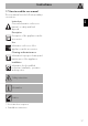
Instructions 1.7 How to read the user manual This user manual uses the following reading conventions: EN Instructions General information on this user manual, on safety and final disposal. Description Description of the appliance and its accessories. Use Information on the use of the appliance and its accessories. Cleaning and maintenance Information for proper cleaning and maintenance of the appliance. Installation Information for the qualified technician: Installation, operation and inspection.
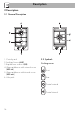
Description 2 Description 2.1 General Description 1. Control panel 2. Auxiliary Burner (AUX) 3. Rapid burner reduced (RR) 4. Ultra-rapid burner with external crown (UR2 int.) 5. Ultra-rapid burner with internal crown (UR2 ext.) 6. Hob grids 2.
Description EN Burner knobs For lighting and adjusting the hob burners. Press and turn the knobs anti-clockwise to The ring must be placed under the hob grid as shown in the picture above. In any case, pans with a diameter greater than 28 cm must be used solely on the Ultra-rapid burner (UR2 int. + UR2 ext.). This ring can also be used with woks. in order to light the relative burners. Turn the knobs to the zone between the maximum and minimum setting to adjust the flame.
Use 3 Use 3.2 First use 3.1 Instructions Improper use Danger of burns • Make sure that the flame-spreader crowns are correctly positioned in their seats with their respective burner caps. • Oils and fats could catch fire if overheated. Be very careful. • Do not leave the appliance unattended during cooking operations where fats or oils could be released. • Do not spray any spray product near the appliance. • Do not touch the appliance’s heating elements when it is running.
Positioning the pan stands Practical tips for using the hob The pan stands are provided unassembled on the hob. To install the grids correctly, follow the instructions as shown in the figure. For better burner efficiency and to minimise gas consumption, use pans with lids and of suitable size for the burner, so that flames do not reach up the sides of the pan. Once the contents come to the boil, turn down the flame far enough to ensure that the liquid does not boil over.
Use Limitations on griddle use A few precautions are necessary if you wish to use a griddle: • The griddles should not exceed the perimeter of the hob. • Aluminium griddles with Teflon anti-stick coating should be pre-heated for a maximum of 5 minutes in order to avoid damage to the appliance and the Teflon coating. After pre-heating, place the foodstuffs on the griddle to cook them; do not exceed 40 minutes of total use for the griddle.
Cleaning and maintenance 4.1 Instructions Improper use Risk of damage to surfaces • Do not use steam jets to clean the appliance. • Do not use cleaning products containing chlorine, ammonia or bleach on parts made of steel or that have metallic surface finishes (e.g. anodizing, nickelor chromium-plating). • Do not use rough or abrasive materials or sharp metal scrapers. • Do not wash the removable components such as the hob grids, flame-spreader crowns and burner caps in a dishwasher. 4.
Cleaning and maintenance Flame-spreader crowns and burner caps Igniters and thermocouples For easier cleaning, the flame-spreader crowns and the burner caps can be removed. Wash them in hot water and nonabrasive detergent. Carefully remove any encrustation, then wait until they are perfectly dry. Refit the flame-spreader crowns making sure that they are correctly positioned in their housings with their respective burner caps.
Installation 5.2 Positioning in the counter top The following operation requires building and/or carpentry work and must therefore be carried out by a competent tradesman. Installation can be carried out on various materials such as masonry, metal, solid wood or plastic laminated wood as long as they are heat resistant (>90°C). 5.1 Safety instructions Heat production during appliance operation Risk of fire • Make sure that the cabinet material is heat resistant.
Installation To prevent leakage of liquid between the frame of the hob and the work surface, carefully put the insulating seal provided in position before assembly. 1. Refer to the dimensions in the figure, bearing in mind that the front and rear long sides must brush against the hole. 4. Carefully trim the surplus away from the edge (B) beyond the seal. 2.
Installation 5.3 Mounting Over built-in oven The clearance between the hob and the kitchen furniture or other installed appliances must be enough to ensure sufficient ventilation and air discharge. If installed above an oven, a space must be left between the bottom of the hob and the top of the appliance installed below.
Installation 5.4 Gas connection Gas leak Danger of explosion opens on rear Over empty kitchen unit or drawers If there are other pieces of furniture (lateral walls, drawers, etc.), dishwashers or fridges under the hob, a double-layer wooden base must be installed at least 10 mm from the bottom of the hob to avoid any accidental contact. It must only be possible to remove the double-layer base using suitable equipment.
Connection with a steel hose Make the connection to the gas mains using a continuous wall steel hose whose specifications comply with the applicable standard. Carefully screw the connector 3 to the gas connector 1 of the appliance, placing the seal 2 between them. Carefully screw the hose connector 3 to the appliance’s gas connector 1 (½” thread ISO 228-1), placing the supplied seal 2 between them. Apply insulating material (½" ISO 7.
Installation Room ventilation The appliance should be installed in rooms that have a permanent air supply in accordance with the standards in force. The room where the appliance is installed must have enough air flow for the regular combustion of gas and the necessary air change in the room itself. The air vents, protected by grilles, must be the right size to comply with current regulations and positioned so that no part of them is obstructed, not even partially.
Installation In case of operation with other types of gas, the burner nozzles must be changed and the minimum flame adjusted on the gas cocks. 3. Replace the burner nozzles using a 7-mm socket wrench according to the gas to be used (see "Nozzle and burner specification tables"). EN 5.5 Adaptation to different types of gas Changing the nozzles 1. Remove the grid from the hob. 2. Remove the flame-spreader crowns and relative burner caps. 4. Replace the burners in their respective housings.
Installation Adjusting the minimum setting for natural or town gas 1. Light the burner and turn it to the minimum position. 2. Remove the knobs by pulling them upwards. 5. Turn the knob rapidly from the maximum to the minimum setting: The flame should not go out. Repeat the operation on all gas cocks. Adjusting the minimum setting for LPG Tighten the screw located at the side of the tap rod clockwise all the way.
Installation Gas types and Countries 1 Natural gas G20 G20 20 mbar G20/25 20/25 mbar 2 Natural gas G20 G20 25 mbar 3 Natural gas G25 G25 25 mbar G25.3 25 mbar 4 Natural gas G25.1 G25.1 25 mbar 5 Natural gas G25 G25 20 mbar 6 Natural gas G2.350 G2.
Installation Burner and nozzle characteristics tables 1 Natural gas G20 - 20 mbar AUX RR UR2 int. UR2 ext. Rated heating capacity (kW) 1.05 2.50 1.00 4.20 Nozzle diameter (1/100 mm) 72 108 80 150 Reduced flow rate (W) 400 800 400 1600 X Y H1 H4 Pre-chamber (printed on nozzle) 2 Natural gas G20 - 25 mbar AUX RR UR int. UR2 ext Rated heating capacity (kW) 1.10 2.50 1.10 4.
9 LPG G30/31 - 30/37 mbar AUX RR UR int. UR2 ext Rated heating capacity (kW) 1.05 2.50 0.90 4.30 Nozzle diameter (1/100 mm) 50 79 46 100 Reduced flow rate (W) 400 800 400 1600 - Z - - Rated flow rate G30 (g/h) 76 182 65 313 Rated flow rate G31 (g/h) 75 179 64 307 AUX RR UR int. UR2 ext Pre-chamber (printed on nozzle) 10 LPG G30/31 - 37 mbar Rated heating capacity (kW) 1.05 2.50 1.00 4.
Installation 5.6 Electrical connection Power voltage Danger of electrocution • Have the electrical connection performed by authorised technical personnel. • Use personal protective equipment. • The appliance must be connected to ground in compliance with electrical system safety standards. • Disconnect the mains power supply. • Do not pull the cable to unplug the appliance. • Use cables withstanding a temperature of at least 90°C. • The tightening torque of the screws of the terminal board leads must be 1.
Testing 5.7 Instructions for the installer At the end of installation, carry out a brief inspection test. If the hob fails to operate, after checking that you have carried out the instructions correctly, unplug the appliance and contact Technical Support. • The plug must be accessible after installation. Do not bend or trap the power cable. • The appliance must be installed according to the installation diagrams. • Do not try to unscrew or force the threaded elbow of the fitting.