Libretto d’uso User manual Manuel d’utilisation Gebrauchsanleitung Gebruiksaanwijzing Manual de uso Livro para utilização KEIV90E
INDICE IT CONSIGLI E SUGGERIMENTI.............................................................................................................................................. 4 CARATTERISTICHE.............................................................................................................................................................. 5 INSTALLAZIONE ..............................................................................................................................................
ÍNDICE PT CONSELHOS E SUGESTÕES............................................................................................................................................ 58 CARACTERÍSTICAS ........................................................................................................................................................... 59 INSTALAÇÃO......................................................................................................................................................
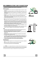
RECOMMENDATIONS AND SUGGESTIONS The Instructions for Use apply to several versions of this appliance. Accordingly, you may find descriptions of individual features that do not apply to your specific appliance. INSTALLATION • The manufacturer will not be held liable for any damages resulting from incorrect or improper installation.
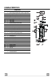
CHARACTERISTICS Components Ref. 1 2 2.1 2.2 3 3.1 3.2 9 14.1 15 16 25 Q.ty 1 1 1 1 1 1 1 1 1 1 1 Product Components Hood Canopy complete with: Controls, Light, Filters Telescopic chimney, made up of: Upper chimney Lower chimney Telescopic panel, made up of: Upper panel Lower panel Reduction flange ø 150-120 mm Air Outlet Connector Extension Air Outlet Connector Novastick tape Hose clamps (not supplied) 21 23 22 11 12g 16 14.1 Q.
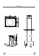
Dimensions Min. Min.
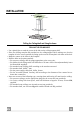
INSTALLATION Drilling the Ceiling/shelf and fixing the frame DRILLING THE CEILING/SHELF • Use a plumb line to mark the centre of the hob on the ceiling/support shelf. • Place the drilling template 21 provided on the ceiling/support shelf, making sure that the template is in the correct position by lining up the axes of the template with those of the hob. • Mark the centres of the holes in the template.
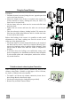
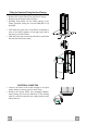
Fixing the Frame/Chimney Should it be necessary to adjust the height of the frame, proceed as follows: • Unfasten the metric screws joining the two opposite parts that can be seen from the front; • Adjust the height of the frame as required, then replace the screws removed as above, making sure that you insert 2 of them close to the panel lock; • Lift the frame, insert the slots onto the screws and slide them until they lock; • Tighten the two screws and insert the other two screws provided.
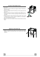
Air outlet – Recirculation Version • Insert the Connector extensions 14.1 into the side of the Connector 15. • Insert the Connector 15 into the Support bracket 7.3 and fix it with the screws. • Fasten the Support bracket 7.3, fixing it to the upper part with the Screws. • Make sure that the Connector extensions outlet 14.1 is in correspondence with the Chimney openings both horizontally and vertically.
Fitting the Panel and Fixing the Hood Canopy Before fixing the Hood Canopy to the Frame: • Remove the Grease filters from the Hood Canopy; • Remove any Activated charcoal filters. • Working from below, fix the Hood canopy to the Frame provided, using the 4 screws 12f (M6 x 10) provided. • Then hook the upper part of the Panel 3, adjusted to size, to the rubber supports in the upper part and in the lower part of the Frame.
USE T1 T2 T3 L Control panel BUTTON LED FUNCTIONS T1 Speed On Turns the Motor on at Speed one. T2 Speed On Turns the Motor on at Speed two. T3 Speed Fixed When pressed briefly, turns the Motor on at Speed three. Flashing Pressed for 2 Seconds. Turns the Motor off. Activates Speed four with a timer set to 6 minutes, after which it returns to the speed that was set previously. Suitable to deal with maximum levels of cooking fumes. L Light Turns the Lighting System on and off.
MAINTENANCE Grease filters CLEANING METAL SELF- SUPPORTING GREASE FILTERS • The filters must be cleaned every 2 months of operation, or more frequently for particularly heavy usage, and can be washed in a dishwasher. • Remove the filters one at a time by pushing them towards the back of the group and pulling down at the same time. • Wash the filters, taking care not to bend them. Allow them to dry before refitting. • When refitting the filters, make sure that the handle is visible on the outside.