Libretto di Istruzioni Instructions Manual Manuel d’Instructions Bedienungsanleitung Gebruiksaanwijzing KDD90VXE-2
INDICE IT CONSIGLI E SUGGERIMENTI.............................................................................................................................................. 3 CARATTERISTICHE.............................................................................................................................................................. 6 INSTALLAZIONE ..............................................................................................................................................
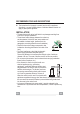
RECOMMENDATIONS AND SUGGESTIONS The Instructions for Use apply to several versions of this appliance. Accordingly, you may find descriptions of individual features that do not apply to your specific appliance. INSTALLATION • The manufacturer will not be held liable for any damages resulting from • • • • • • incorrect or improper installation.
• If the instructions for installation for the gas hob specify a greater distance specified above, this has to be taken into account. Regulations concerning the discharge of air have to be fulfilled. • Use only screws and small parts in support of the hood. Warning: Failure to install the screws or fixing device in accordance with these instructions may result in electrical hazards. • Connect the hood to the mains through a two-pole switch having a contact gap of at least 3 mm.
• “CAUTION: Accessible parts may become hot when used with cooking appliances.” MAINTENANCE • Switch off or unplug the appliance from the mains supply before carrying out • • • • • any maintenance work. Clean and/or replace the Filters after the specified time period (Fire hazard). The Grease filters must be cleaned every 2 months of operation, or more frequently for particularly heavy usage, and can be washed in a dishwasher.
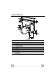
CHARACTERISTICS Components Ref. 1 2 3 4 Ref. 7.1 7.2 7.3 12a 12b 12c EN Q.ty 1 1 1 1 Q.ty 2 2 2 16 6 Q.ty 1 Product Components Hood Canopy complete with: Controls, Light, Filters Motor unit Electric unit Front Frame Installation Components Splashback Fixing Bracket Hob Fixing Bracket Side Bracket Screws 3.5 x 9.
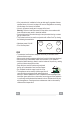
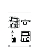
Dimensions 512 - 7 94 537 - 880 537 - 8 80 520 - 8 02 512 - 794 520 - 802 EN 262
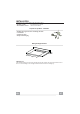
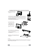
INSTALLATION This Hood is set up to be fitted inside the kitchen unit in: • Ducting version: Evacuation to the outside. • Recirculation version: Internal recirculation.
Inserting the Hood Canopy into the support surface from below • The Hood is built ready for front installation of the Motor Unit. • If the kitchen unit is arranged differently and the Motor Unit has to be fitted on the back, the Plug already fitted on the back of the Hood Canopy must be removed and replaced at the front, and the Cable with cable raceway for connection of the Motor must also be repositioned using the slot provided on each side (A).
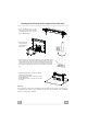
Inserting the Hood Canopy into the support surface from above 7.2 • Insert the Brackets 7.2, as indicated in the figure, into the slots provided and fix them with the screws 12a provided. 12a 7.2 12a • The Hood is built ready for front installation of the Motor Unit.
Fixing the Lower Brackets • Screw the brackets 7.1 to the front of the Hood Canopy using the screws 12a provided. • Before tightening the Brackets completely, make all the adjustments to allow them to rest on the lower base of the worktop to avoid deformation of the upper brackets 7.2 (Only for KDD90VXE-2) as shown in the figure. 12a 7.1 7.1 12a • With the aid of a spirit level, set the Hood Canopy level vertically and fix it to the Lower Surface using 2 screws 12c provided.
Fixing the Squaring Brackets • Screw the brackets 7.3 to the Hood Canopy using the screws 12b provided, without tightening completely. • Using the screws 12c provided, fasten the other part of the brackets 7.3 either to the side walls of the unit or to the lower part of the cooker top. 7.3 12b 7.3 12b 12c • Tighten the screws 12c and 12b completely.
Fixing the Motor Unit • Installation of the Motor Unit (1) at the front or rear must be decided according to the position of the Kitchen unit, making sure that the plug is properly positioned. • Subsequently, according to where the air outlet opening has been created on the unit, the Motor Unit can be turned by 90° at a time so as to allow the air to come out on all 4 sides in correspondence with the opening in Unit (2). • Connect the connector from the Hood Canopy to the Motor Unit connection.
Fixing the Electric Unit • Connect the Electric cables that come out of the lower right hand part of the Hood Canopy to the Connectors on the Electric unit. • Each cable connector has a corresponding connector on the Electric Unit, so take care not to make mistakes when connecting up. • Fix the Electric Unit to the Hood Canopy using the screws 12a provided.
Connections DUCTED VERSION AIR EXHAUST SYSTEM When installing the ducted version, connect the hood to the chimney using either a flexible or rigid pipe ø 150 or 120 mm, the choice of which is left to the installer. • To install a ø 120 mm air exhaust connection, insert the reducer flange 9 on the hood body outlet. • Fix the pipe in position using sufficient pipe clamps (not supplied). • Remove possible charcoal filters.
Fitting the Front element • Lift the mobile hood canopy (see paragraph on Use) by just a few centimetres. • To stop movement, simply press down on the mobile canopy as it lifts up. Warning: Never block the sliding door when it is opening or closing, except during the operations required to fit the frame. Warning..: Handle with care • Remove the sponge guards from the corners of the glass.
Surround Suction Panel • Open the Hood Door (see USE). • Remove the 2 strips of adhesive tape fastening the panel during transport.
USE Control panel But ton A B C D E F G Function The button only works when the door is open. Turns the motor On/Off at speed one. Press and hold the button for approximately 5 seconds, with all the loads turned off (Motor and Lights), to turn the Remote control On/Off. Press Briefly = Turns the Lights On/Off at maximum intensity. Press and hold for 2 Seconds = Turns the Courtesy Lights On/Off. The button only works when the door is open.
REMOTE CONTROL (OPTIONAL) The appliance can be controlled using a remote control powered by a 1.5 V carbon-zinc alkaline batteries of the standard LR03-AAA type (not included). • Do not place the remote control near to heat sources. • Used batteries must be disposed of in the proper manner. Remote control panel Warning..: The remote control receiver is deactivated when first supplied. To activate it, see the paragraph Use.
MAINTENANCE Cleaning the Comfort Panels • • • • • • Open the Comfort Panel by pulling it at the top. Unhook the security chain by opening the spring catch. Disconnect the panel from the hood canopy. The comfort panel must never be washed in the dishwasher. Clean the outside with a damp cloth and neutral detergent. Clean the inside using a damp cloth and neutral detergent; do not use wet cloths or sponges, or jets of water; do not use abrasive substances.
Activated Charcoal Filter (Recirculation Version) Can be washed in the dishwasher. It must be washed when is displayed or at least once every 4 months, or more frequently if use is particularly intense. Guaranteed to operate after washing for up to a maximum of 5 times before requiring replacement. The Alarm signal, if it has been activated, only appears when the Suction motor is turned on.