Table of contents 1.1 1.2 1.3 1.4 1.5 1.6 1.7 General safety instructions Manufacturer liability Appliance purpose Identification plate This user manual Disposal How to read the user manual 2 Description 2.1 2.2 2.3 2.4 2.5 General Description Cooking hob Control panel Other parts Available accessories 3 Use 3.1 3.2 3.3 3.4 3.5 3.6 Instructions Cleaning the surfaces Cleaning the hob Cleaning the door Cleaning the oven cavity Extraordinary maintenance 5 Installation 5.1 5.2 5.3 5.4 5.
Instructions 1 Instructions 1.1 General safety instructions Risk of personal injury • During use the appliance and its accessible parts become very hot. Never touch the heating elements during use. • Protect your hands by wearing oven gloves when moving food inside the oven. • Never try to put out a fire or flames with water: turn off the appliance and smother the flames with a fire blanket or other appropriate cover.
• While cooking do not place metal objects, such as cutlery or dishes on the hob surface as they may overheat. • Do not insert pointed metal objects (cutlery or utensils) into the slots in the appliance. • Do not pour water directly on very hot trays. • Keep the oven door closed during cooking. • If you need to move food or at the end of cooking, open the door 5 cm for a few seconds, let the steam come out, then open it fully.
Instructions Risk of damaging the appliance • Do not use abrasive or corrosive detergents (e.g. scouring powders, stain removers and metallic sponges) on glass parts. • Use wooden or plastic utensils. • Racks and trays should be inserted as far as they will go into the side guides. The mechanical safety locks that prevent them from being removed must face downwards and towards the back of the oven. • Do not sit on the appliance. • Do not use steam jets to clean the appliance.
• All pans must have smooth, flat bottoms. • If any liquid does boil over or spill, remove the excess from the hob. • Take care not to spill acid substances such as lemon juice or vinegar on the hob. • Do not put empty pans or frying pans on switched on cooking zones. • Do not use steam jets to clean the appliance. • Do not use rough or abrasive materials or sharp metal scrapers.
Instructions • Installation using a hose must be carried out so that the length of the hose does not exceed 2 metres when fully extended for steel hoses and 1.5 metres for rubber hoses. • The hoses should not come into contact with moving parts and should not be crushed in any way. • If required, use a pressure regulator that complies with current regulations. • After carrying out any operation, check that the tightening torque of gas connections is between 10 Nm and 15 Nm.
1.2 Manufacturer liability The manufacturer declines all liability for damage to persons or property caused by: • use of the appliance other than that specified; • failure to comply with the instructions in the user manual; • tampering with any part of the appliance; • use of non-original spare parts. 1.3 Appliance purpose • This appliance is intended for cooking food in the home environment. Every other use is considered inappropriate.
Instructions • Deliver the appliance to the appropriate recycling centre for electrical and electronic equipment waste, or return it to the retailer when purchasing an equivalent product, on a one for one basis. Our appliances are packaged in non-polluting and recyclable materials. • Deliver the packing materials to the appropriate recycling centre. Plastic packaging Danger of suffocation • Do not leave the packaging or any part of it unattended. • Do not let children play with the plastic bags. 1.
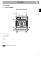
Description 2 Description EN 2.
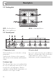
Description 2.2 Cooking hob AUX = Auxiliary burner SR = Semi-rapid burner UR-3c = Ultra-rapid burner 2.3 Control panel 1 Temperature knob 3 Function knob This knob allows you to select the cooking temperature. Turn the knob clockwise to the required value, between the minimum and maximum setting. The oven’s various functions are suitable for different cooking modes. After selecting the required function, set the cooking temperature using the temperature knob.
Description Cooling fan 4 Timer knob EN Allows you to set manual cooking or a timer with automatic oven switch off at the end of cooking. 5 Hob burner knobs Used for lighting and adjusting the hob burners. Press and turn the knobs anticlockwise to in order to light the relative burners. Turn the knobs to the zone between the maximum and minimum setting to adjust the flame. Return the knobs to the position burners. to turn off the The fan cools the appliance and comes into operation during cooking.
Description 2.5 Available accessories Ring reducer Rack Useful when using small cookware. Lid Useful for supporting containers with food during cooking. Deep tray The toughened glass lid with aluminium edging protects the hob when not in use. Useful for collecting fat from foods placed on the rack above and for cooking pies, pizzas and baked desserts.
Description EN Evaporation tray and cover Used to distribute the steam inside the oven. The maximum capacity of the evaporation tray is 250 ml. Not all accessories are available on some models. The oven accessories intended to come into contact with food are made of materials that comply with the provisions of current legislation. Original supplied and optional accessories can be requested to Authorised Assistance Centres. Use only original accessories supplied by the manufacturer.
Use 3 Use 3.1 Instructions High temperature inside the oven during use Danger of burns • Keep the oven door closed during cooking. • Protect your hands wearing heat resistant gloves when moving food inside the oven. • Do not touch the heating elements inside the oven. • Do not pour water directly on very hot trays. • Keep children under the age of 8 away from the oven when it is in use.
Use • Do not spray any spray product near the appliance. • Do not use or leave flammable materials near the appliance or the storage compartment. • Do not use plastic cookware or containers for cooking. • Do not place sealed tins or containers in the oven cavity. • Do not leave the appliance unattended during cooking operations where fats and oils could be released. • Remove all trays and racks which are not required during cooking.
Use First use Racks and trays 1. Remove any protective film from the outside or inside of the appliance, including accessories. 2. Remove any labels (apart from the technical data plate) from the accessories and from the oven cavity. 3. Remove and wash all the appliance's accessories (see 4 Cleaning and maintenance). 4. Heat the empty oven at the maximum temperature to burn off any residues left by the manufacturing process.
Use All the appliance’s control and monitoring devices are located together on the front panel. The burner controlled by each knob is shown next to the knob. The appliance is equipped with an electronic ignition device. Simply press the knob and turn it counterclockwise to the maximum flame symbol, until the burner ignites. If the burner does not light in the first 15 seconds, turn the knob to and wait 60 seconds before trying again.
Use 3.4 Using the oven Switching on the oven To switch the oven on: 1. Select manual cooking or set the cooking duration using the timer knob. Adjustment is progressive so that the time can also be set to any intermediate value between these numbers. 2. Select the temperature using the temperature knob. 3. Select the cooking function using the function knob. 4. At the end of timed cooking, a buzzer sounds that stops automatically after a few seconds.
Fan with grill The air produced by the fan softens the strong heatwave generated by the grill, grilling perfectly even very thick foods. Perfect for large cuts of meat (e.g. shin of pork). Direct Steam This function activates the central part of the lower heating element together with the circulaire heating element and fan, allowing the food to be cooked by the evaporation of the water in the tray.
Use 3. Fill the tray with sufficient water for the cooking duration (see Direct Steam cooking information table). 4. 5. 6. 7. Put the cover back on the tray. Place the food on the oven tray. Place the tray with the food in the oven. Select the Direct Steam function using the function knob. 8. Select the cooking temperature and time using the appropriate knobs. For best results and to save energy, it is recommended to fill the tray with sufficient water for the required cooking.
Use 5. Use a sponge to remove any condensation from the base and walls of the oven cavity, the door glass and the drip tray at the front of the appliance. 3.6 Cooking advice General advice • Use a fan assisted function to achieve consistent cooking at several levels. • It is not possible to shorten cooking times by increasing the temperature (the food could be overcooked on the outside and undercooked on the inside).
Use Advice for cooking desserts/pastries and biscuits • Use dark metal moulds: They help to absorb the heat better. • The temperature and the cooking time depend on the quality and consistency of the dough. • When cooking on multiple levels, food should ideally be positioned on the second and fourth shelves; increase cooking time by a few minutes and only used fan functions.
Use Food Lasagne Pasta bake Weight (Kg) Function Shelf Temperature (°C) Time (minutes) 3-4 3-4 Static Static 1 1 220 - 230 220 - 230 45 - 50 45 - 50 Fan assisted Fan assisted Fan with grill Fan assisted Circulaire/Fan assisted Fan assisted Fan assisted Fan assisted 2 2 4 2 2 2 2 2 180 - 190 180 - 190 260 200 180 - 190 180 - 190 180 - 190 180 - 190 Veal roast 2 Pork loin 2 Sausages 1.5 Roast beef 1 Roast rabbit 1.5 Turkey breast 3 Roast pork neck 2 - 3 Roast chicken 1.
Use Direct Steam cooking information table Food Lasagne Pasta bake Weight (Kg) Water (ml) Shelf Temperature (°C) Time (minutes) 1.6 120 - 130 2 190 - 200 35 - 40 1.2 - 1.5 120 - 130 2 190 - 200 35 - 40 MEAT Roast turkey 1.5 180 2 190 - 200 80 - 90 Pork loin Roast rabbit (pieces) Spare ribs (attached) Leg of lamb (well done) 1.5 180 2 190 - 200 85 - 90 1 160 2 180 - 190 80 - 90 0.
Use Weight (Kg) Water (ml) 1 80 0.6 80 Temperature (°C) Time (minutes) 2 210 - 220 40 - 45 2 210 35 Shelf EN Food VEGETABLES Roast potatoes Mixed roasted vegetables REHEATING FOOD Pasta Sliced roasted meats / spare 0.3 100 - 110 2 120 15 - 25 0.5 100 - 110 2 120 15 - 25 Bread 0.5 100 - 110 2 120 15 - 25 Strudel 0.5 100 - 110 2 120 15 - 25 DESSERTS/PASTRIES Bundt cake Strudel Muffins Paradise cake Sponge cake Biscuits (0.
Cleaning and maintenance 4 Cleaning and maintenance 4.2 Cleaning the surfaces 4.1 Instructions To keep the surfaces in good condition, they should be cleaned regularly after use. Let them cool first. Improper use Risk of damage to surfaces • Do not use steam jets to clean the appliance. • Do not use cleaning products containing chlorine, ammonia or bleach on parts made of steel or that have metallic surface finishes (e.g. anodizing, nickelor chromium-plating).
4.3 Cleaning the hob Igniters and thermocouples Cooking hob grids For correct operation the igniters and thermocouples must always be perfectly clean. Check them frequently and clean them with a damp cloth if necessary. Remove any dry residues with a wooden toothpick or a needle. Remove the grids and clean them in lukewarm water and non-abrasive detergent. Make sure to remove any encrustations. Dry them thoroughly and return them to the hob.
Cleaning and maintenance 2. Unscrew the screws on the back of the hinges. 4.4 Cleaning the door Removing the door For easier cleaning, the door can be removed and placed on a towel. To remove the door proceed as follows: 1. Open the door completely and insert two pins into the holes on the hinges indicated in the figure. 3. Open it and lift it upwards. 4. Clean. 5. Insert the lid into the guides. Tighten the fastening screws on the hinges in closed position.
3. To reassemble the door, put the hinges in the relevant slots in the oven, making sure that grooved sections A are resting completely in the slots. Lower the door and once it is in position, remove the pins from the holes in the hinges. Cleaning the door glazing The door glazing should always be kept thoroughly clean. Use absorbent kitchen roll. In case of stubborn dirt, wash with a damp sponge and an ordinary detergent. 3. Remove the intermediate glazing pane by lifting it upwards.
Cleaning and maintenance 6. Reposition the internal glass pane. Take care to centre and insert the 4 pins into their housings in the oven door by applying slight pressure. Take out all removable parts. 4.5 Cleaning the oven cavity For the best oven cavity upkeep, clean it regularly after having allowed it to cool. Avoid letting food residue dry inside the oven cavity, as this could damage the enamel.
Cleaning of racks and trays Cleaning the evaporation tray and cover Clean the racks and trays with warm water and non-abrasive detergents. Carefully rinse and dry damp parts. It is recommended that you clean and dry the evaporation tray and the perforated cover after using the Direct Steam function. Common cleaning products can be used: avoid using products that are too harsh and/or acidic. The cover and the tray can be washed in a dishwasher.
Cleaning and maintenance 2. Carefully lift the end of the lower heating element by a few centimetres and clean the bottom of the oven. Seal maintenance tips The seal should be soft and elastic. • To keep the seal clean, use a nonabrasive sponge and wash with lukewarm water. Replacing the internal light bulb Live parts Danger of electrocution • Unplug the appliance from the mains. • Wear protective gloves. Put the heating element back into its seat when finished.
Cleaning and maintenance EN 4. Slide out and remove the light bulb. Do not touch the halogen light bulb directly with your fingers, use an insulating material. 5. Replace the light bulb with one of the same type (40 W). 6. Refit the cover. Ensure the moulded part of the glass (A) is facing the door. 7. Press the cover down as far as it will go so that it attaches completely to the bulb support.
Installation 5 Installation 5.1 Gas connection (not valid for the UK) For installation in the UK, please refer to the “Local specifications for UK gas appliances installation” booklet. Gas leak Danger of explosion • After carrying out any operation, check that the tightening torque of gas connections is between 10 Nm and 15 Nm. • If required, use a pressure regulator that complies with current regulations. • At the end of the installation, check for any leaks with a soapy solution, never with a flame.
Installation Connection with a steel hose Make the connection to the gas mains using a continuous wall steel hose whose specifications comply with the applicable standard. Carefully screw the connector 3 to the gas connector 1 of the appliance, placing the seal 2 between them. Connection with a steel hose with bayonet fitting Connection using a rubber hose complying with current standards is only permitted if the hose can be inspected along its entire length.
Installation Connection to LPG Room ventilation Use a pressure regulator and make the connection on the gas cylinder following the guidelines set out in the standards in force. The appliance should be installed in rooms that have a permanent air supply in accordance with the standards in force. The room where the appliance is installed must have enough air flow for the regular combustion of gas and the necessary air change in the room itself.
Installation 5.2 Adaptation to different types of gas EN Improper installation Risk of malfunction • In the case of conversion to Town Gas G110 – 8 mbar (category 1a), do not use the burners provided, but request the special G110 burners kit from our Technical Assistance Service.
Installation (see "Nozzle and burner specification tables"). Adjusting the minimum setting for LPG Tighten the screw located at the side of the cock rod clockwise all the way. Following adjustment to a gas other than the one originally set in the factory, replace the gas setting label on the appliance with the one corresponding to the new gas. The label is inserted inside the nozzle pack (where present). 3. Reposition the burners in their respective housings.
Installation Gas types and Countries IT GB-IE FR-BE DE AT NL ES PT SE RU DK PL HU Gas types 1 Natural gas G20 20 mbar • • • • • • • • • • EN G20 • G20/25 20/25 mbar 2 Natural gas G20 G20 • 25 mbar 3 Natural gas G25 G25 25 mbar G25.3 25 mbar • • 4 Natural gas G25.1 G25.1 • 25 mbar 5 Natural gas G25 G25 • 20 mbar 6 Natural gas G2.350 G2.
Installation Burner and nozzle characteristics tables 1 Natural gas G20 - 20 mbar Rated heating capacity (kW) Nozzle diameter (1/100 mm) Pre-chamber (printed on nozzle) Reduced flow rate (W) 2 Natural gas G20 - 25 mbar Rated heating capacity (kW) Nozzle diameter (1/100 mm) Pre-chamber (printed on nozzle) Reduced flow rate (W) 3 Natural gas G25/G25.3 - 25 mbar Rated heating capacity (kW) Nozzle diameter (1/100 mm) Pre-chamber (printed on nozzle) Reduced flow rate (W) 4 Natural gas G25.
Installation AUX 1.05 50 400 76 75 AUX 1.1 50 450 80 79 AUX 1.05 43 (H2) 400 76 75 AUX 1.05 145 8 400 SR 1.8 65 500 131 129 SR 1.8 65 550 131 129 SR 1.8 58 (M) 500 131 129 SR 1.8 185 2 500 UR-3c 3.5 94 1600 255 250 UR-3c 3.5 91 1600 255 250 UR-3c 3.5 75 (F4) 1600 255 250 UR-3c 3.
Installation 5.3 Positioning Heavy appliance Crushing hazard • Position the appliance into the cabinet cut-out with the help of a second person. Pressure on the open door Risk of damage to the appliance • Never use the oven door to lever the appliance into place when fitting. • Avoid exerting too much pressure on the door when open. Any wall units positioned above the worktop of the appliance must be at a minimum distance of at least Y mm.
Installation EN Appliance overall dimensions B - Class 2 subclass 1 (Built-in appliance) A 600 mm B 600 mm C1 D min. 150 mm 900 - 915 mm H 750 mm I 450 mm L2 600 mm 1 Minimum distance from side walls or other flammable material. 2 Minimum cabinet width (=A). C - Class 2 subclass 1 (Built-in appliance) The appliance must be installed by a qualified technician and according to the regulations in force.
Installation Dimensions of the appliance: locations of gas and electric connections (mm) Positioning and levelling Heavy appliance Risk of damage to the appliance • Insert the front feet first and then the rear ones. After making the electrical and/or gas connections, screw the four adjustable feet supplied with the appliance. A 124 B 32 C 42 D 628 F min. 70 - max. 105 H 770 L 598 E = Electrical connection G = Gas connection 96 The appliance must sit level on the floor to ensure stability.
Installation Fastening to the wall 3. Assemble the fastening bracket. EN The anti-tip devices must be installed in order to prevent the appliance from tipping over. 1. Screw the wall fastening plate to the rear of the appliance. 2. Adjust the height of the 4 feet. 4. Align the base of the hook on the fastening bracket with the base of the slot on the wall fastening plate.
Installation 5. Align the base of the fastening bracket with the ground and tighten the screws to fix the measurements. 6. Use 50 mm for the distance from the side of the appliance to the bracket holes. 98 7. Move the bracket onto the wall and mark the position of the holes to be drilled in the wall. 8. After drilling the holes in the wall, use wall plugs and screws to fasten the bracket to the wall. 9.
Installation Fitting the lid 3. Lower the lid onto the hob. 2. Install the lid from above, parallel with the two supports A. EN 1. Install the two supports A and fasten them from below the hob using the corresponding screws B. 4. Fasten the lid to the hob using the screws C inserted in the rear of the two supports A.
Installation 5.4 Instructions for the installer • The plug must be accessible after installation. Do not bend or trap the power cable. • The appliance must be installed according to the installation diagrams. • Do not try to unscrew or force the threaded elbow of the fitting. You may damage this part of the appliance, which may void the manufacturer’s warranty. • Use soap and water to check for gas leaks on all connections. DO NOT use naked flames when looking for leaks.
Installation EN The appliance can work in the following modes: • 220-240 V 1N~ 3 x 1.5 mm² three-core cable. The values indicated above refer to the cross-section of the internal lead. The aforementioned power cables are sized taking into account the coincidence factor (in compliance with standard EN 60335-2-6). Fixed connection Fit the power line with an all-pole disconnection switch, with at least 3 mm between its contacts, in compliance with installation regulations.