Table of contents 1.1 1.2 1.3 1.4 1.5 1.6 1.7 General safety instructions Manufacturer liability Appliance purpose Identification plate This user manual Disposal How to read the user manual 2 Description 2.1 2.2 2.3 2.4 2.5 General Description Cooking hob Control panel Other parts Available accessories 3 Use 3.1 3.2 3.3 3.4 3.5 Instructions Cleaning the surfaces Cleaning the hob Cleaning the door Cleaning the oven cavity Vapor Clean (on some models only) Extraordinary maintenance 5 Installation 5.1 5.
Instructions 1 Instructions 1.1 General safety instructions Risk of personal injury • During use the appliance and its accessible parts become very hot. Never touch the heating elements during use. • Protect your hands by wearing oven gloves when moving food inside the oven. • Never try to put out a fire or flames with water: turn off the appliance and smother the flames with a fire blanket or other appropriate cover.
• While cooking do not place metal objects, such as cutlery or dishes on the hob surface as they may overheat. • Do not insert pointed metal objects (cutlery or utensils) into the slots in the appliance. • Do not pour water directly on very hot trays. • Keep the oven door closed during cooking. • If you need to move food or at the end of cooking, open the door 5 cm for a few seconds, let the steam come out, then open it fully.
Instructions Risk of damaging the appliance • Do not use abrasive or corrosive detergents (e.g. scouring powders, stain removers and metallic sponges) on glass parts. • Use wooden or plastic utensils. • Racks and trays should be inserted as far as they will go into the side guides. The mechanical safety locks that prevent them from being removed must face downwards and towards the back of the oven. • Do not sit on the appliance. • Do not use steam jets to clean the appliance.
• All pans must have smooth, flat bottoms. • If any liquid does boil over or spill, remove the excess from the hob. • Take care not to spill acid substances such as lemon juice or vinegar on the hob. • Do not put empty pans or frying pans on switched on cooking zones. • Do not use steam jets to clean the appliance. • Do not use rough or abrasive materials or sharp metal scrapers.
Instructions • Installation using a hose must be carried out so that the length of the hose does not exceed 2 metres when fully extended for steel hoses and 1.5 metres for rubber hoses. • The hoses should not come into contact with moving parts and should not be crushed in any way. • If required, use a pressure regulator that complies with current regulations. • After carrying out any operation, check that the tightening torque of gas connections is between 10 Nm and 15 Nm.
1.3 Appliance purpose • This appliance is intended for cooking food in the home environment. Every other use is considered inappropriate. • The appliance is not designed to operate with external timers or with remote-control systems. 1.4 Identification plate The identification plate bears the technical data, serial number and brand name of the appliance. Do not remove the identification plate for any reason. 1.
Instructions • Deliver the appliance to the appropriate recycling centre for electrical and electronic equipment waste, or return it to the retailer when purchasing an equivalent product, on a one for one basis. Our appliances are packaged in non-polluting and recyclable materials. • Deliver the packing materials to the appropriate recycling centre. Plastic packaging Danger of suffocation • Do not leave the packaging or any part of it unattended. • Do not let children play with the plastic bags. 1.
Description 2 Description EN 2.
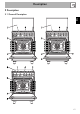
Description 1 Cooking hob 2 Control panel 3 Light bulb 4 Seal 5 Door 6 Fan 7 Lid (on some models only) 8 Upstand (on some models only) 9 Pizza stone (on some models only) Rack/tray support frames 64
Description EN 2.
Description 2.
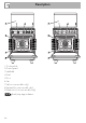
1 Temperature knob 5 Hob burner knobs This knob allows you to select the cooking temperature. Turn the knob clockwise to the required value, between the minimum and maximum setting. Used for lighting and adjusting the hob burners. Press and turn the knobs anticlockwise to in order to light the relative burners. Turn the knobs to the zone between the maximum and minimum 2 Indicator light The indicator light comes on to indicate that the oven is heating up.
Description 2.5 Available accessories Cooling fan Rack The fan cools the appliance and comes into operation during cooking. The fan causes a steady outflow of air that exits from the rear of the appliance and which may continue for a brief period of time even after the appliance has been turned off. Useful for supporting containers with food during cooking. Deep tray Do not obstruct ventilation openings and heat dispersal slots.
Description Pizza stone cover (on some models only) The toughened glass lid with aluminium edging protects the hob when not in use. To be placed in the housing on the base of the oven in place of the pizza stone when this is not being used. EN Lid (on some models only) Pizza stone (on some models only) Not all accessories are available on some models. The oven accessories intended to come into contact with food are made of materials that comply with the provisions of current legislation.
Use 3 Use 3.1 Instructions High temperature inside the oven during use Danger of burns • Keep the oven door closed during cooking. • Protect your hands wearing heat resistant gloves when moving food inside the oven. • Do not touch the heating elements inside the oven. • Do not pour water directly on very hot trays. • Keep children under the age of 8 away from the oven when it is in use.
Use • Do not spray any spray product near the appliance. • Do not use or leave flammable materials near the appliance or the storage compartment. • Do not use plastic cookware or containers for cooking. • Do not place sealed tins or containers in the oven cavity. • Do not leave the appliance unattended during cooking operations where fats and oils could be released. • Remove all trays and racks which are not required during cooking.
Use First use Racks and trays 1. Remove any protective film from the outside or inside of the appliance, including accessories. 2. Remove any labels (apart from the technical data plate) from the accessories and from the oven cavity. 3. Remove and wash all the appliance's accessories (see 4 Cleaning and maintenance). 4. Heat the empty oven at the maximum temperature to burn off any residues left by the manufacturing process.
Use Always hold the pizza spatula by the handle to put food in and take it out of the oven. You are advised to dust the steel surface lightly with flour to make it easier to slide fresh products on and off, as they could stick to the steel due to their moisture content.
Use 3.3 Using the hob All the appliance’s control and monitoring devices are located together on the front panel. The burner controlled by each knob is shown next to the knob. The appliance is equipped with an electronic ignition device. Simply press the knob and turn it counterclockwise to the maximum flame symbol, until the burner ignites. If the burner does not light in the first 15 seconds, turn the knob to and wait 60 seconds before trying again.
3.4 Using the oven Switching on the oven (models with minute minder knob) To switch the oven on: 1. Select manual cooking or set the cooking duration using the timer knob. Adjustment is progressive so that the time can also be set to any intermediate value between these numbers. 2. Select the temperature using the temperature knob. 3. Select the cooking function using the function knob. 4. At the end of timed cooking, a buzzer sounds that stops automatically after a few seconds.
Use Fan with grill The air produced by the fan softens the strong heatwave generated by the grill, grilling perfectly even very thick foods. Perfect for large cuts of meat (e.g. shin of pork). Fan assisted (on some models only) The operation of the fan, combined with traditional cooking, ensures consistent cooking even with complex recipes. Perfect for biscuits and cakes, even when simultaneously cooked on several levels. (For multiple-level cooking, we recommend using the 2nd and 4th runners).
Use When using the ECO function, avoid opening the door during cooking. Cooking (and preheating) times are longer with the ECO function. Vapour Clean This function makes cleaning easier using the steam produced by a little quantity of water poured onto the appropriate groove placed on the bottom. (see chapter “Cleaning and maintenance”) 3.5 Cooking advice General advice • Use a fan assisted function to achieve consistent cooking at several levels.
Use • When using the Fan with grill function, we recommend that you preheat the oven before grilling. • We recommend placing the food at the centre of the rack. • With the Grill function, we recommend that you turn the temperature knob to the maximum value to optimise cooking. Advice for cooking desserts/pastries and biscuits • Use dark metal moulds: They help to absorb the heat better. • The temperature and the cooking time depend on the quality and consistency of the dough.
Use Cooking information table Function Shelf Temperature (°C) Time (minutes) Lasagne Pasta bake 3-4 3-4 Static Static 1 1 220 - 230 220 - 230 45 - 50 45 - 50 Roasted veal Pork loin Sausages Roast beef Roast rabbit Turkey breast Roast pork neck Roast chicken 2 2 1.5 1 1.5 3 2-3 1.
Cleaning and maintenance 4 Cleaning and maintenance 4.1 Instructions Improper use Risk of damage to surfaces • Do not use steam jets to clean the appliance. • Do not use cleaning products containing chlorine, ammonia or bleach on parts made of steel or that have metallic surface finishes (e.g. anodizing, nickelor chromium-plating). • Do not use abrasive or corrosive detergents (e.g. scouring powders, stain removers and metallic sponges) on glass parts.
4.3 Cleaning the hob Igniters and thermocouples Cooking hob grids For correct operation the igniters and thermocouples must always be perfectly clean. Check them frequently and clean them with a damp cloth if necessary. Remove any dry residues with a wooden toothpick or a needle. Remove the grids and clean them in lukewarm water and non-abrasive detergent. Make sure to remove any encrustations. Dry them thoroughly and return them to the hob.
Cleaning and maintenance Glass lid (on some models only) For easier cleaning, the lid can be taken off its hinges. 1. Lower the lid to closed position. 3. Open it and lift it upwards. 4. Clean. 5. Insert the lid into the guides. Tighten the fastening screws on the hinges in closed position. If liquids fall on the lid when it is closed, carefully remove them with a cloth before opening it. Knobs 2. Unscrew the screws on the back of the hinges.
4.4 Cleaning the door Removing the door For easier cleaning, the door can be removed and placed on a towel. To remove the door proceed as follows: 1. Open the door completely and insert two pins into the holes on the hinges indicated in the figure. 3. To reassemble the door, put the hinges in the relevant slots in the oven, making sure that grooved sections A are resting completely in the slots. Lower the door and once it is in position, remove the pins from the holes in the hinges.
Cleaning and maintenance Removing the internal glass panes For easier cleaning, the internal glass panes of the door can be removed. 1. Remove the internal glass pane by pulling the rear part gently upwards following the movement indicated by the arrows (1). This way, the 4 pins attached to the glass detach from their housings in the door. 2. Then, pull the front part upwards (2). 3. Remove the intermediate glazing pane by lifting it upwards.
4.5 Cleaning the oven cavity Cleaning of racks and trays For the best oven cavity upkeep, clean it regularly after having allowed it to cool. Avoid letting food residue dry inside the oven cavity, as this could damage the enamel. Take out all removable parts. Clean the racks and trays with warm water and non-abrasive detergents. Carefully rinse and dry damp parts. Removing racks/trays support frames Removing the guide frames enables the sides to be cleaned more easily.
Cleaning and maintenance Cleaning the roof of the oven (on some models only) Cleaning the pizza stone (on some models only) 1. Remove in sequence the pizza stone cover (1) and the base (2) on which it is placed. The base has to be lifted a few millimetres, then pulled outwards. The pizza stone should be washed separately according to the following instructions: The stone must be cleaned after every use. Do not heat it again if it has any encrustations.
Cleaning and maintenance Vapor Clean is an assisted cleaning procedure which facilitates the removal of dirt. Thanks to this process, it is possible to clean the inside of the oven very easily. The dirt residues are softened by the heat and water vapour for easier removal afterwards. Improper use Risk of damage to surfaces • Remove any large amounts of food residues or spills from previous cooking operations from the inside of the oven.
Cleaning and maintenance • For multifunction models and models with pizza stone: spray a water and washing up liquid solution inside the oven using a spray nozzle. Direct the spray against the side walls, upwards, downwards and towards the deflector. Vapor Clean cycle setting (models without minute minder timer knob) 1. Turn the function knob to the symbol and the temperature knob to the symbol . 2. Calculate a Vapour Clean cleaning cycle of 18 (use a minute minder timer). 3.
Cleaning and maintenance End of the Vapor Clean cycle 4.7 Extraordinary maintenance 4. Open the door and wipe away the less stubborn dirt with a microfibre cloth. 5. Use a non-scratch sponge with brass filaments on hard to remove deposits. 6. In case of grease residues use specific oven cleaning products. 7. Remove the water left inside the oven.
Cleaning and maintenance Replacing the internal light bulb 4. Slide out and remove the light bulb. Live parts Danger of electrocution • Unplug the appliance from the mains. • Wear protective gloves. 1. Remove all accessories from inside the oven cavity. 2. Remove the rack/tray support frames. 3. Remove the bulb cover using a tool (e.g. a screwdriver). Take care not to scratch the enamel of the oven cavity wall. Do not touch the halogen light bulb directly with your fingers, use an insulating material. 5.
Installation 5.1 Gas connection (not valid for the UK) For installation in the UK, please refer to the “Local specifications for UK gas appliances installation” booklet. Gas leak Danger of explosion • After carrying out any operation, check that the tightening torque of gas connections is between 10 Nm and 15 Nm. • If required, use a pressure regulator that complies with current regulations. • At the end of the installation, check for any leaks with a soapy solution, never with a flame.
Installation Carefully screw the hose connector 3 to the appliance’s gas connector 1 (½” thread ISO 228-1), placing the seal 2 between them. The hose connector 4 can also be screwed to the hose connector 3, depending on the diameter of the gas hose used. After having tightened the hose connector(s), push the gas hose 6 onto the hose connector and secure it with the clamp 5 that is compliant with the standard in force.
Connection to LPG Room ventilation Use a pressure regulator and make the connection on the gas cylinder following the guidelines set out in the standards in force. The appliance should be installed in rooms that have a permanent air supply in accordance with the standards in force. The room where the appliance is installed must have enough air flow for the regular combustion of gas and the necessary air change in the room itself.
Installation 5.2 Adaptation to different types of gas Improper installation Risk of malfunction • In the case of conversion to Town Gas G110 – 8 mbar (category 1a), do not use the burners provided, but request the special G110 burners kit from our Technical Assistance Service.
Installation Adjusting the minimum setting for LPG Tighten the screw located at the side of the cock rod clockwise all the way. Following adjustment to a gas other than the one originally set in the factory, replace the gas setting label on the appliance with the one corresponding to the new gas. The label is inserted inside the nozzle pack (where present). 3. Reposition the burners in their respective housings.
Installation Gas types and Countries IT GB-IE FR-BE DE AT NL ES PT SE RU DK PL HU Gas types 1 Natural gas G20 G20 20 mbar • • • • • • • • • • G20/25 20/25 mbar 2 Natural gas G20 G20 • 25 mbar 3 Natural gas G25 G25 25 mbar G25.3 25 mbar • • 4 Natural gas G25.1 G25.1 • 25 mbar 5 Natural gas G25 G25 • 20 mbar 6 Natural gas G2.350 G2.
Installation 1 Natural gas G20 Rated heating capacity (kW) Nozzle diameter (1/100 mm) Pre-chamber (printed on nozzle) Reduced flow rate (W) 2 Natural gas G20 Rated heating capacity (kW) Nozzle diameter (1/100 mm) Pre-chamber (printed on nozzle) Reduced flow rate (W) 3 Natural gas G25 Rated heating capacity (kW) Nozzle diameter (1/100 mm) Pre-chamber (printed on nozzle) Reduced flow rate (W) 4 Natural gas G25.
Installation 7 LPG G30/31 Rated heating capacity (kW) Nozzle diameter (1/100 mm) Pre-chamber (printed on nozzle) Reduced flow rate (W) Rated flow rate G30 (g/h) Rated flow rate G31 (g/h) 8 LPG G30/31 Rated heating capacity (kW) Nozzle diameter (1/100 mm) Pre-chamber (printed on nozzle) Reduced flow rate (W) Rated flow rate G30 (g/h) Rated flow rate G31 (g/h) 9 LPG G30/31 Rated heating capacity (kW) Nozzle diameter (1/100 mm) Pre-chamber (printed on nozzle) Reduced flow rate (W) Rated flow rate G30 (g/h) Rat
5.3 Positioning Heavy appliance Crushing hazard • Position the appliance into the cabinet cut-out with the help of a second person. Pressure on the open door Risk of damage to the appliance • Never use the oven door to lever the appliance into place when fitting. • Avoid exerting too much pressure on the door when open. Any wall units positioned above the worktop of the appliance must be at a minimum distance of at least Y mm.
Installation Appliance overall dimensions B - Class 2 subclass 1 (Built-in appliance) A 600 mm B 600 mm C1 D min. 150 mm 900 - 915 mm H 750 mm I 450 mm L2 600 mm 1 Minimum distance from side walls or other flammable material. 2 Minimum cabinet width (=A). C - Class 2 subclass 1 (Built-in appliance) The appliance must be installed by a qualified technician and according to the regulations in force.
Installation Positioning and levelling Heavy appliance Risk of damage to the appliance • Insert the front feet first and then the rear ones. After making the electrical and/or gas connections, screw the four adjustable feet supplied with the appliance. A 124 B 32 C 42 D 628 F min. 70 - max. 110 H 770 L 598 The appliance must sit level on the floor to ensure stability. Screw or unscrew the bottom part of the foot until the appliance is stable and level on the floor.
Installation Fastening to the wall 3. Assemble the fastening bracket. The anti-tip devices must be installed in order to prevent the appliance from tipping over. 1. Screw the wall fastening plate to the rear of the appliance. 2. Adjust the height of the 4 feet. 102 4. Align the base of the hook on the fastening bracket with the base of the slot on the wall fastening plate.
Installation 7. Move the bracket onto the wall and mark the position of the holes to be drilled in the wall. EN 5. Align the base of the fastening bracket with the ground and tighten the screws to fix the measurements. 6. Use 50 mm for the distance from the side of the appliance to the bracket holes. 8. After drilling the holes in the wall, use wall plugs and screws to fasten the bracket to the wall. 9.
Installation Fitting the lid 3. Lower the lid onto the hob. 1. Install the two supports A and fasten them from below the hob using the corresponding screws B. 2. Install the lid from above, parallel with the two supports A. 104 4. Fasten the lid to the hob using the screws C inserted in the rear of the two supports A.
Installation The upstand provided is an integral part of the product; it must be fastened to the appliance prior to installation. The upstand must always be positioned and secured correctly on the appliance. 1. Unscrew the 2 nuts (B) on the back of the hob. 2. Position the upstand above the hob, taking care to align the pins (C) with the holes (D). 3. Secure the upstand to the hob by tightening the screws (A). 5.4 Instructions for the installer • The plug must be accessible after installation.
Installation 5.5 Electrical connection Power voltage Danger of electrocution • Have the electrical connection performed by authorised technicians. • Use personal protective equipment. • The appliance must be connected to ground in compliance with electrical system safety standards. • Disconnect the mains power supply. • Do not pull the cable to remove the plug. • Use cables withstanding a temperature of at least 90 °C. • The tightening torque of the screws of the terminal board leads must be 1.5 - 2 Nm.