Contents 1.1 1.2 1.3 1.4 1.5 1.6 General safety instructions Identification plate Manufacturer liability Appliance purpose This user manual How to read the user manual 2 Description 2.1 2.2 2.3 2.4 2.5 General Description Cooktop Control panel Other parts Available accessories 3 Use 3.1 3.2 3.3 3.4 3.5 3.6 3.7 3.8 Instructions Cleaning the appliance Removing the door Cleaning the door glazing Removing the internal glass panes Vapour Clean Extraordinary maintenance 5 Installation 5.1 5.2 5.3 5.4 5.5 5.
Instructions 1 Instructions 1.1 General safety instructions Risk of personal injury • During use the appliance and its accessible parts become very hot. • Never touch the heating elements during use. • Keep children under eight years of age at a safe distance if they are not constantly supervised. • Children must never play with the appliance.
Risk of damaging the appliance • Do not use abrasive or corrosive detergents on glass parts (e.g. powder products, stain removers and metallic sponges). • Racks and trays have to be inserted into the side guides until they come to a complete stop. The mechanical safety locks that prevent the rack from being taken out accidentally have to face downwards and towards the oven back. • Use wooden or plastic utensils. • Do not seat on the appliance. • Do not use steam jets for cleaning the appliance.
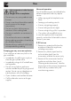
Instructions 1.4 Appliance purpose 1.6 How to read the user manual • This appliance is intended for cooking food in the home environment. Every other use is considered improper. • The appliance is not designed to operate with external timers or with remote-control systems. This user manual uses the following reading conventions: 1.
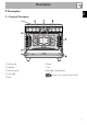
Description EN 2 Description 2.
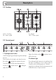
Description 2.2 Cooktop AUX = Auxiliary SR = Semi-rapid R = Rapid UR2 = Ultra rapid 2.3 Control panel 1 Cooktop burner knobs Useful for lighting and adjusting the cooktop burners. Press and turn the knobs anti-clockwise to the value to light the relative burners. Turn the knobs to the zone between the maximum and minimum setting to adjust the flame. 8 Return the knobs to the off the burners. position to turn 2 Indicator light The indicator light comes on to indicate that the oven is heating up.
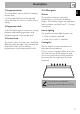
3 Temperature knob 2.4 Other parts This knob allows you to select the cooking temperature. Turn the knob clockwise to the required value, between the minimum and maximum setting. Shelves 4 Programmer clock Useful for displaying the current time, setting programmed cooking operations and programming the minute minder timer. 5 Function knob The oven's various functions are suitable for different cooking modes. After selecting the required function, set the cooking temperature using the temperature knob.
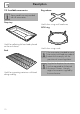
Description 2.5 Available accessories Ring reducer Some models are not provided with all accessories. Deep tray Useful when using small cookware. WOK ring Useful for collecting fat from foods placed on the rack above. Rack Useful for supporting containers with food during cooking. 10 Useful when using a wok. The accessories intended to come into contact with food are made of materials that comply with the provisions of current legislation.
Use 3.1 Instructions High temperature inside the oven during use Danger of burns • Keep the oven door closed during cooking. • Protect your hands wearing heat resistant gloves when moving food inside the oven. • Do not touch the heating elements inside the oven. • Do not pour water directly onto very hot trays. • Do not allow children younger than 8 years old to come near the appliance when in operation.
Use High temperature inside the oven during use Danger of fire or explosion • Do not spray any spray products near the oven. • Do not use or leave flammable materials near the oven or the storage compartment. • Do not use plastic kitchenware or containers when cooking food. • Do not put sealed tins or containers in the oven. • Do not leave the oven unattended during cooking operations where fats or oils could be released. • Remove all trays and racks which are not required during cooking.
3.3 Using the accessories Racks and trays Ring reducers Racks and trays have to be inserted into the side guides until they come to a complete stop. • The mechanical safety locks that prevent the rack from being taken out accidentally have to face downwards and towards the oven back. The ring reducers have to be placed on the cooktop grids. Make sure they are placed properly. Gently insert racks and trays into the oven until they come to a stop.
Use 3.4 Using the cooktop All the appliance's control and monitoring devices are located together on the front panel. The burner controlled by each knob is shown next to the knob. The appliance is equipped with an electronic ignition device. Simply press the knob and turn it anticlockwise to the maximum flame symbol, until the burner lights. If the burner does not light in the first 15 seconds, turn the knob to and wait 60 seconds before trying again.
3.5 Using the storage compartment Preheating stage There is a storage compartment located at the bottom of the cooker; this can be used to store pans or metal objects required to use the cooker. Press lightly on the sides of the door to open it. Cooking functions are always preceded by a preheating stage, which allows the appliance to heat up to cooking temperature. The indicator light comes on to indicate that the oven is heating up.
Use Small grill Using only the heat released from the central element, this function enables small portions of meat and fish to be grilled for making kebabs, toasted sandwiches and all types of grilled vegetable side dishes. The rotisserie is not present on this appliance. The rotisserie is only available as a kit purchased separately.
3.7 Cooking advice Rapid defrost Rapid defrost is helped by switching on the fan provided and the top heating element that ensure uniform distribution of low temperature air inside the oven. Eco Using the grill and the lower heating element in combination is particularly suitable for cooking on a single shelf, as it provides low energy consumption. Ideal for cooking meat, fish and vegetables. Not recommended for desserts which must rise.
Use • Foods should be seasoned before cooking. Foods should also be coated with oil or melted butter before cooking. • Use the oven tray on the first bottom shelf to collect fluids produced by grilling. • Grilling processes should never last more than 60 minutes. Advice for cooking desserts/pastries and biscuits • Use dark metal moulds: they help to absorb the heat better. • The temperature and the cooking time depend on the quality and consistency of the dough.
Use Setting the time EN 3.8 Programmer clock If the time is not set, the oven will not switch on. On the first use, or after a power failure, the digits will be flashing on the appliance’s display. 1. Press the keys and at the same time. The dot between the hours and the minutes flashes. 2.
Use Timed cooking Timed cooking is the function which allows a cooking operation to be started and then ended after a specific length of time set by the user. 1. After selecting a cooking function and temperature, press the key . The display will show the digits and the symbol displayed between the hours and the minutes. 2. Use the key or to set the required minutes. 3. Wait approx. 5 seconds without pressing any key in order for the function to activate.
3. Use the key or to set the required minutes. 4. Wait approx. 5 seconds without pressing any key in order for the function to activate. The current time and the Minute minder timer symbols and will appear on the display. 5. At the end of cooking the heating elements will be deactivated. On the The minute minder timer can be activated at any time. display, the symbol turns off, the symbol flashes and the buzzer sounds. 6. To turn off the buzzer just press any key of the programmer clock. 7.
Use Cooking information table Lasagne Pasta bake 3-4 3-4 Convection Convection Runner position from the bottom 1 1 Roast veal Pork Sausages Roast beef Roast rabbit Turkey breast Roast pork neck Roast chicken 2 2 1.5 1 1.5 3 2-3 1.
Cleaning and maintenance Cleaning the cooktop grids, flamespreader crowns and burner caps 4.1 Instructions 1. Remove the components from the cooktop. 2. Clean them with warm water and nonabrasive detergent. Make sure to remove any encrustations. 3. Dry thoroughly with a soft cloth or a microfibre cloth. Improper use Risk of damage to surfaces • Do not use steam jets to clean the appliance.
Cleaning and maintenance Recommendations for cleaning the oven cavity For the best oven upkeep, clean it regularly after having allowed it to cool. Avoid letting food residue dry inside the oven cavity, as this could damage the enamel. Take out all removable parts before cleaning. For easier cleaning, we recommend removing: • The door • The rack/tray support frames • The oven seal.
4.5 Removing the internal glass panes For easier cleaning the door internal glass panes can be disassembled. 1. Remove the internal glass pane by pulling the rear part gently upwards, following the movement indicated by the arrows (1). 2. Then, pull the front part upwards (2). In this way, the 4 pins attached to the glass detach from their housings in the oven door. 4. Clean the external glass pane and the panes previously removed. Use absorbent kitchen roll.
Cleaning and maintenance Removing racks/trays support frames Removing the guide frames enables the sides to be cleaned more easily. This operation should be performed each time the automatic cleaning cycle is used (on some models only). To remove the guide frames: Pull the frame towards the inside of the oven to unhook it from its groove A, then slide it out of the seats B at the back. When cleaning is complete, repeat the above procedures to put the guide frames back in. 4.
• Pour approximately 40 cc of water into the tray. Make sure it does not overflow out of the cavity. Vapour Clean setting 1. Turn the function knob to the symbol the temperature knob to the symbol and . 2. Set a cooking time of 18 minutes using the programmer clock. The Vapour Clean cycle starts a few seconds after the last press on the programmer clock keys. 3.
Cleaning and maintenance 4.7 Extraordinary maintenance 4. Slide out and remove the light bulb. Replacing the oven light bulb Live parts Danger of electrocution • Unplug the appliance. The oven is fitted with a 40W light bulb. 1. Completely remove all accessories from inside the oven. 2. Remove the racks/trays support frames. 3. Remove the bulb cover using a tool (e.g. a screwdriver). Do not touch the halogen light bulb directly with your fingers, but wrap it in insulating material. 5.
Removing and installing the oven seal What to do if... To remove the oven seal: • Unhook the clips in the 4 corners and in the centre, then pull the oven seal. The appliance does not work. • The circuit breaker is faulty: look in the fuse box and check that the circuit breaker is in working order. • Power cut: check whether the kitchen light works. The gas burner does not ignite. • Power cut or damp ignition plugs: light the gas burner with a gas lighter or a match. The oven does not heat up.
Installation 5 Installation 5.1 Clearances above and around domestic appliances This appliance must be installed by an authorised person in accordance with this instruction manual, AS/NZS 5601.1 – Gas installations (installation and pipe sizing), local gas fitting regulations, local electrical regulations, Building Code of Australia and any other government authority. Requirements 1.
Installation Notes 1. Requirement 3 does not apply to a freestanding or elevated cooking appliance which is designed to prevent flames or the cooking vessels from extending beyond the periphery of the appliance. 2. The ‘cooking surface area’ is defined as that part of the appliance where cooking normally takes place and does not include those parts of the appliance containing control knobs. 3. For definition of cooktop, see Clause 1.4.64. 4. For definition of trivet, see Clause 1.4.109. 5.
Installation Connection of the appliance to the gas supply must be in accordance with the requirements of AS5601. A ½” BSP connector at the inlet is recommended and the gas supply line to the appliance must be of adequate length to allow sufficient withdrawal of appliance for service or disconnection and be: 1. annealed copper pipe or; 2. flexible hose according to AS/NZ1869 & be at least Class “B”, 10 mm diameter.
Installation EN Connection to liquid gas Use a pressure regulator and make the connection on the gas cylinder following the guidelines set out in the regulations in force. Make sure that the supply pressure complies with the values indicated in section “ Burner and nozzle characteristics table”. Room ventilation The room containing the appliance should have a permanent air supply in accordance with the standards in force.
Installation 5.3 Adaptation to different types of gas In case of operation with other types of gas, the burner nozzles must be changed and the minimum flame adjusted on the gas cocks. Turn the knob rapidly from the maximum to the minimum setting: the flame should not go out. Repeat the operation on all gas cocks. Replacing nozzles 1. Remove the pan stands, burner caps and flame-spreader crowns to access the burner casings. 2.
Burner and nozzle characteristics table 1 ULPG 2.75 kPa AUX SR R UR int. UR est. Nominal gas consumption (MJ/h) Injector (1/100 mm) 3.9 54 6.3 68 10.8 88 4.0 50 14.0 100 2 NG 1.0 kPA AUX SR R UR int. UR est. Nominal gas consumption (MJ/h) Injector (1/100 mm) 3.9 90 7.5 120 12 155 4.0 90 14.0 175 Overall dimensions Location of gas and electrical connection points. 5.
Installation General information This appliance may be installed next to walls, one of which must be higher than the worktop, at a minimum distance of 50 mm from the side of the appliance, as shown in figures A and C relative to the installation classes. Any wall units positioned above the worktop must be at a minimum distance of at least 600 mm. If a hood is installed above the cooktop, refer to the hood instruction manual to ensure the correct clearance is left.
Positioning and levelling Heavy appliance Risk of damage to the appliance • Insert the front feet first and then the rear ones. • After making the gas and electrical connections, screw on the four feet supplied with the appliance. The appliance must sit level on the floor to ensure stability. • Screw or unscrew the bottom part of the foot until the appliance is stable and level on the floor. Assembling the backguard The backguard provided is an integral part of the product.
Installation Fastening to the wall 3. Assemble the fastening bracket. The anti-tip devices must be installed in order to prevent the appliance tipping over. 1. Screw the wall fastening plate to the rear of the appliance. 4. Align the base of the hook on the fastening bracket with the base of the slot on the wall fastening plate. 2. Adjust the height of the 4 feet.
Installation 6. Use 50 mm for the distance from the side of the appliance to the bracket holes. 7. Move the bracket onto the wall and mark the position of the holes to be drilled in the wall. EN 5. Align the base of the fastening bracket with the ground and tighten the screws to fix the measurements. 8. After drilling the holes in the wall, use wall plugs and screws to fasten the bracket to the wall. 9.
Installation Wall fixing 1. Turn the screw placed behind the cooktop near the gas connection. 4. Mark the wall in the position where the hole is to be drilled. 5. Drill the hole and insert a wall plug. 2. Attach the chain to the cooker with the screw just removed. 3. Stretch it out horizontally so that the other end of the chain touches the wall. 40 6. Attach the chain and push the appliance to the wall.
Installation Power voltage Danger of electrocution • Have the electrical connection performed by authorised technical personnel. • Use personal protective equipment. • The appliance must be connected to earth in compliance with electrical system safety standards. • Disconnect the mains supply. • Do not pull the cable to remove the plug. • Use cables withstanding a temperature of at least 90°C. • The tightening torque of the screws of the terminal board conductors must be 1.5 - 2 Nm.
Installation 5.6 For the installer • The plug must remain accessible after the installation is complete. Do not kink or trap the mains connection cable. • The appliance must be fitted according to the installation diagrams. • Do not attempt to turn or stress the threaded elbow on the manifold. You risk damage to this part of the appliance which may void the manufacturer’s warranty. • Before leaving check all connections for gas leaks with soap and water. DO NOT use a naked flame for detecting leaks.