Contents 1.1 1.2 1.3 1.4 1.5 1.6 1.7 General safety instructions Appliance purpose Manufacturer liability This user manual Identification plate Disposal How to read the user manual 2 Description 2.1 2.2 2.3 2.4 2.5 General Description Cooking hob Control panel Other parts Available accessories 3 Use 79 83 83 84 84 84 85 86 86 87 87 88 89 91 3.1 Instructions 3.2 First use 3.3 Using the accessories 3.4 Using the hob 3.5 Using the oven 3.6 Cooking advice 3.7 Special functions 3.8 Automatic programs 3.
Contents 5 Installation 5.1 5.2 5.3 5.4 5.
1 Instructions 1.1 General safety instructions Risk of personal injury • During use the appliance and its accessible parts become very hot. Never touch the heating elements during use. • Protect your hands by wearing oven gloves when moving food inside the oven • Never try to put out a fire or flames with water: Turn off the appliance and smother the flames with a fire blanket or other appropriate cover.
Instructions • The cooking process must always be monitored. A short cooking process must be continuously monitored. • Do not place metal objects, such as dishes or cutlery, on the hob surface during use as they may overheat. • Do not insert pointed metal objects (cutlery or utensils) into the slots in the appliance. • Do not pour water directly onto very hot trays. • Keep the oven door closed during cooking.
Risk of damaging the appliance • Do not use abrasive or corrosive detergents (e.g. scouring powders, stain removers and metallic sponges) on glass parts. • Use wooden or plastic utensils. • Racks and trays should be inserted as far as they will go into the side guides. The mechanical safety locks that prevent them from being removed must face downwards and towards the back of the oven • Do not seat on the appliance. • Do not use steam jets to clean the appliance.
Instructions • If any liquid does boil over or spill, remove the excess from the hob. • Take care not to spill acid substances such as lemon juice or vinegar on the hob. • Do not put empty pans or frying pans on switched on cooking zones. • Do not use steam jets to clean the appliance. • Do not use rough or abrasive materials or sharp metal scrapers. • Do not use cleaning products containing chlorine, ammonia or bleach on parts made of steel or that have metallic surface finishes (e.g.
• The hoses should not come into contact with moving parts and should not be crushed in any way. • If required, use a pressure regulator that complies with current regulations. • After carrying out any operation, check that the tightening torque of gas connections is between 10 Nm and 15 Nm. • At the end of the installation, check for any leaks with a soapy solution, never with a flame. • Have the electrical connection performed by authorised technical personnel.
Instructions 1.4 This user manual This user manual is an integral part of the appliance and must therefore be kept in its entirety and within the user’s reach for the whole working life of the appliance. Read this user manual carefully before using the appliance. 1.5 Identification plate The identification plate bears the technical data, serial number and brand name of the appliance. Do not remove the identification plate for any reason. 1.
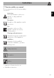
Instructions 1.7 How to read the user manual This user manual uses the following reading conventions: EN Instructions General information on this user manual, on safety and final disposal. Description Description of the appliance and its accessories. Use Information on the use of the appliance and its accessories, cooking advice. Cleaning and maintenance Information for proper cleaning and maintenance of the appliance.
Description 2 Description 2.
Description EN 2.2 Cooking hob AUX = Auxiliary SR = Semi-rapid R = Rapid DUAL = Ultra-rapid 2.3 Control panel 1 Hob burner knobs Used for lighting and adjusting the hob burners. Press and turn the knobs anti-clockwise to in order to light the relative burners. Turn the knobs to the zone between the maximum and minimum flame. setting to adjust the Return the knobs to the position off the burners.
Description 3 Display Interior lighting Displays the current time, the selected cooking temperature and function and any time set. The appliance’s interior lighting comes on: • When the door is opened. • When any function is selected, apart from the + and functions 4 Function knob This knob allows you to turn the appliance on and off and select the cooking function. 2.4 Other parts Cooling fan The fan cools the oven and comes into operation during cooking.
Description 2.5 Available accessories Oven tray EN WOK ring Useful when using a wok. Useful for collecting fat from foods placed on the rack above. Tray rack Deep tray To be placed over the top of the oven tray; for cooking foods which may drip. Useful for collecting fat from foods placed on the rack above and for cooking pies, pizzas and baked desserts.
Description Rack Some models are not provided with all accessories. The accessories intended to come into contact with food are made of materials that comply with the provisions of current legislation. Useful for supporting containers with food during cooking. Rotisserie (on some models only) Useful for cooking chicken and all foods which require uniform cooking over their entire surface. 90 Supplied and optional accessories can be requested to Authorised Assistance Centres.
Use 3.1 Instructions High temperature inside the oven during use Danger of burns • Keep the oven door closed during cooking. • Protect your hands by wearing oven gloves when moving food inside the oven. • Do not touch the heating elements inside the oven. • Do not pour water directly onto very hot trays. • Keep children under the age of 8 away from the appliance when it is in use.
Use High temperature inside the oven during use Danger of fire or explosion • Do not spray any spray products near the appliance. • Do not use or leave flammable materials near the appliance or the storage compartment. • Do not use plastic cookware or containers when cooking food. • Do not put sealed tins or containers in the oven. • Do not leave the appliance unattended during cooking operations where fats or oils could be released. • Remove all trays and racks which are not required during cooking.
3.3 Using the accessories Racks and trays Ring reducers Racks and trays have to be inserted into the side guides until they come to a complete stop. The mechanical safety locks that prevent the rack from being taken out accidentally have to face downwards and towards the oven back. The ring reducers must be placed on the hob grids. Make sure they are placed properly. Tray rack The tray rack has to be inserted into the tray.
Use Rotisserie (on some models only) 1. Insert the 4 supplied bushings in the 4 corner holes of the deep tray and screw them onto the ring nuts with a suitable tool (such as a screwdriver). 2. Position the rotisserie supports in the bushings as shown in the figure below. 94 3. Prepare the rotisserie rod with the food using the clip forks provided. The clip forks can be tightened using the fastening screws. 4. Once you have prepared the rotisserie rod, place it on the supports.
Use 7. To activate the rotisserie, turn the function knob to select the + function and use the temperature knob to set a cooking temperature. Pour a little water into the tray to prevent smoke from forming. 8. When cooking is complete, remove the tray with the rotisserie. 9. Screw on the handle provided so that you can handle the rotisserie rod more easily. These operations must be performed with the oven off and cold. 95 EN 5. Place the tray on the first runner (see “General Description”). 6.
Use 3.4 Using the hob All the appliance’s control and monitoring devices are located together on the front panel. The burner controlled by each knob is shown next to the knob. The appliance is equipped with an electronic ignition device. Simply press the knob and turn it anticlockwise to the maximum flame symbol, until the burner ignites. If the burner does not light in the first 15 seconds, turn the knob to and wait 60 seconds before trying again.
Use 3.5 Using the oven Before lighting the hob burners, make sure that the grids are correctly positioned on the hob. Bear in mind that: • Each grid has its own position on the hob. • The raised section must always face the appliance's upstand.
Use Operating modes Stand-by: When no function is selected, the display shows the current time. Each time the temperature knob is pressed during a function, the parameters will be cycled through in the following order. Temperature Minute minder timer duration Function duration Programmed cooking duration (if timed cooking has been selected) ON: When a function is activated, the display shows the parameters set such as temperature, duration and temperature reached.
Use When using the appliance for the first time, or after a power failure, the symbol will flash on the display. To be able to start any cooking function, the current time must be set. 1. Turn the temperature knob to set the displayed time (keep the knob turned to produce a faster increase or decrease). 2. Press the temperature knob. 3. Turn the temperature knob to set the minutes (keep the knob turned to produce a faster increase or decrease). 4. Press the temperature knob to finish adjustment.
Use Functions list Eco This function is particularly suitable for cooking on a single shelf with low energy consumption. Ideal for cooking meat, fish and vegetables. It is not recommended for leavened foods. To obtain maximum energy savings and reduce cooking times, it is recommended to place food in the oven without preheating. When using the ECO function, avoid opening the door during cooking. Cooking (and preheating) times are longer with the ECO function.
Use Circulaire The combination of the fan and the circulaire heating element (incorporated in the rear of the oven) allows you to cook different foods on several levels, as long as they need the same temperature and type of cooking. Hot air circulation ensures instant and even distribution of heat. It will be possible, for instance, to cook fish, vegetables and biscuits simultaneously (on different levels) without odours and flavours mingling.
Use 4. To deactivate the buzzer, press or turn one of the two knobs. 5. To select a further minute minder, turn the temperature knob. 2. Turn the temperature knob right or left to set the cooking duration from 00:01 to 12:59. Keep the knob turned to produce a faster increase or decrease. You must set the value to zero to remove the minute minder. Timed cooking Timed cooking is the function which allows a cooking operation to be started and then ended after a specific length of time set by the user.
Use To deactivate the buzzer and select a further timed cooking, turn the temperature knob to the right. To deactivate the buzzer and select a different cooking function, turn the function knob to the right or left. Press and hold the function knob down to switch off the appliance. Programmed cooking Programmed cooking is the function which allows cooking to be stopped at an established time depending on the time set by the user, after which the appliance will switch off automatically. 1.
Use 3. Press the temperature knob a fourth time. The indicator light flashes. Turn the knob right or left to set the cooking end time. 5. At the end of cooking, is shown on the display and a buzzer sounds. 4. After a few seconds the indicator lights and stop flashing. The appliance waits for the set start time. 6. To deactivate the buzzer, press or turn one of the two knobs or open the door. Press and hold the function knob down to switch off the appliance.
Use After modifying the cooking duration, the end of cooking time must be re-set. During operation, it is possible to modify programmed cooking duration: 1. When the indicator lights and are lit steadily and the appliance is waiting for cooking to start, press the temperature knob twice. The indicator light starts flashing. 2. Turn the temperature knob right or left to alter the pre-set cooking time. 3. Press the temperature knob again.
Use Advice for cooking desserts/pastries and biscuits • Use dark metal moulds: They help to absorb the heat better. • The temperature and the cooking time depend on the quality and consistency of the dough. • In the case of multiple-level cooking, position the food preferably on the 2nd and 4th shelves, increase the cooking time by a few minutes and use only fanassisted functions.
Use 3.7 Special functions Proving EN Defrost by time 1. Place the food inside the oven. 2. Press and turn the function knob to select the defrost by time function . 3. Turn the temperature knob to set the duration (from 1 to 99 minutes). 4. Press the temperature knob to confirm the set duration. flashes. 5. Press the function knob to start the defrost by time function. 6. At the end, is displayed and a buzzer sounds. 7. To deactivate the buzzer, press or turn one of the two knobs or open the door.
Use Sabbath This function allows food to be cooked in accordance with the provisions of the Jewish religion day of rest. This function results in the appliance operating in a particular way: • Cooking can proceed indefinitely, it is not possible to set any time. • No preheating will be performed. • The cooking temperature which can be selected varies between 60-100 °C. • Oven light disabled, any operation such as opening the door or manual activation with the knob will not activate the light.
5. Turn the temperature knob to select the weight (in grams) of the food to defrost. 6. Press the function knob to confirm the parameters and start defrosting. Defrost by weight This function defrosts foods on the basis of the type and weight of the frozen products. 1. Place the food inside the oven. 2. Press and turn the function knob to select defrost by weight, marked by 7. At the end, is displayed and a buzzer sounds. 8. To deactivate the buzzer, press or turn one of the two knobs or open the door.
Use 3.8 Automatic programs 5. When preheating has finished, will flash. Introduce the food and then press the function knob to start cooking. The automatic cooking programs are divided up according to the type of dish to be cooked. 1. Press and turn the function knob to select cooking with automatic programs, marked by and the illuminated food symbols . 2. Press the function knob to confirm cooking with automatic programs. 3.
Use Automatic programs table Pr 01 Subcategory Roast beef (cooked medium) Weight Level (g) Function Temperature Time (°C) (minutes) 1300 2 200 56 02 Roast pork 800 2 190 88 03 Lamb (cooked medium) 2000 2 190 105 04 Veal 1000 2 190 80 05 Roast chicken (whole) 1000 2 200 80 FISH (06 - 07) Pr Subcategory Weight Level (g) Function Temperature Time (°C) (minutes) 06 Fresh fish (whole) 500 2 160 35 07 Frozen fish 600 2 160 50 VEGETABLES (08 - 10) Pr Subcategory Weigh
Use DESSERTS/PASTRIES (11 - 13) Pr Subcategory Weight Level (g) Function Temperature Time (°C) (minutes) 11 Biscuits 500 2 160 23 12 Muffins 500 2 160 21 13 Tart 1000 2 170 43 BREAD - PIZZA - PASTA (14 - 20) Pr Subcategory Weight Level (g) Function Temperature Time (°C) (minutes) 14 Leavened bread (loaf) 1000 2 200 27 15 Pan baked pizza 1000 2 280 12 16 Stone baked pizza 500 1* 280 7 17 Pasta bake 2000 1 220 35 18 Lasagne 2000 1 230 40 19 Paella 500 2 190
3.9 Secondary menu Child lock mode The appliance also has a drop-down secondary menu allowing the user to: • Activate or deactivate the Child lock. • Activate or deactivate Showroom mode (which disables all the heating elements so that only the control panel works). • Activate or deactivate Eco-Logic mode. • Activate or deactivate Keep Warm mode. • Activate or deactivate Eco-light mode.
Use To release the lock temporarily during cooking, hold the temperature knob down for 5 seconds. One minute after the last setting the lock will become active again. Showroom mode (for exhibitors only) This mode allows the appliance to deactivate all heating elements, while keeping the control panel active. When the position of the knobs is changed, the display will show for a few seconds.
Low power (Eco-logic) mode: Keep Warm mode This mode allows the appliance to limit the power used. Suitable for simultaneous use with further home appliances. HI: normal power. This mode allows the appliance to keep cooked food warm (at low temperatures) for around an hour after cooking finishes with a cooking cycle for which a duration has been set (if this is not manually interrupted). LO: low power. Activating eco-logic mode means that preheating and cooking times may be extended.
Use Eco-light mode 3.10 Using the storage compartment For greater energy savings, the light is automatically deactivated one minute from the start of cooking. There is a storage compartment located at the bottom of the cooker; this can be used to store pans or metal objects required for its use. 1. To open the storage compartment, press lightly on the left-hand side of the door until it clicks. To stop the appliance from automatically deactivating the light after one minute, set this mode to OFF. 2.
Cleaning and maintenance 4.1 Instructions Improper use Risk of damage to surfaces • Do not use steam jets to clean the appliance. • Do not use cleaning products containing chlorine, ammonia or bleach on parts made of steel or that have metallic surface finishes (e.g. anodizing, nickelor chromium-plating). • Do not use abrasive or corrosive detergents (e.g. scouring powders, stain removers and metallic sponges) on glass parts. • Do not use rough or abrasive materials or sharp metal scrapers.
Cleaning and maintenance Cleaning the igniters and thermocouples • If necessary, clean the igniters and thermocouples with a damp cloth. • If there is any dry residue, remove it with a toothpick or needle. For easier cleaning, we recommend removing: • The door • The rack/tray support frames • Removable guides, where fitted • The seal In the event you are using specific cleaning products, we recommend running the oven at maximum temperature for 15-20 minutes in order to eliminate any residue. 4.
Cleaning and maintenance 3. To reassemble the door, put the hinges in the relevant slots in the oven, making sure that grooved sections A are resting completely in the slots. Lower the door and once it is in place remove the pins from the holes in the hinges. Removing the internal glass panes For easier cleaning the internal glass panes of the door can be removed. 1. Pull the rear part of the internal glass pane gently upwards, following the movement indicated by the arrows (1). 2.
Cleaning and maintenance 3. Remove the intermediate glass pane by lifting it upwards. Removing racks/trays support frames Removing the rack/tray support frames enables the sides to be cleaned more easily. To remove the rack/tray support frames: • Pull the frame towards the inside of the oven to unhook it from its groove A, then slide it out of the seats B at the back. The pyrolytic model has two intermediate glass panes. 4. Clean the external glass pane and the panes removed previously.
Cleaning and maintenance Manual deactivation of the door lock lever (pyrolytic models only) 1. Move the door lock lever to the right until it stops. EN Improper use Danger of burns • The following operations must always be performed with the appliance cold and switched off. • Never attempt to manually deactivate the door lock lever during a pyrolytic cycle. The door lock lever is located in the first slot on the left under the control panel, in the upper part of the front of the oven.
Cleaning and maintenance Cleaning the top section (not on pyrolytic models) The oven cavity is fitted with a tilting heating element which facilitates cleaning the top part (roof) of the oven. 1. Free the upper heating element by gently lifting it and rotating its retainers by 90 degrees. 4.5 Vapor Clean (on some models only) Vapor Clean is an assisted cleaning procedure which facilitates the removal of dirt. Thanks to this process, it is possible to clean the inside of the oven very easily.
Cleaning and maintenance Vapor Clean cycle setting If the internal temperature is greater than that required for the Vapor Clean cycle, the cycle will be stopped immediately and the message will appear on the display. Let the appliance cool down before activating the assisted cleaning cycle. 1. Press and turn the function knob to select the Vapor Clean function . The duration and temperature of the cleaning cycle will appear on the display.
Cleaning and maintenance Programmed Vapor Clean cycle End of the Vapor Clean cycle Like for the normal cooking functions, it is also possible to set an end time for the Vapor Clean function. 1. After selecting the Vapor Clean function, press the temperature knob. The indicator light starts flashing. The display shows the function end time. At the end, is displayed and a buzzer sounds. 1. To deactivate the buzzer, press or turn one of the two knobs or open the door. 2.
Cleaning and maintenance Pyrolytic cleaning is an automatic high-temperature cleaning procedure which causes dirt to dissolve. Thanks to this process, it is possible to clean the inside of the oven very easily. Improper use Risk of damage to surfaces • Remove any food residues or large spills from previous cooking operations from the inside of the oven. Preliminary operations Before starting the pyrolytic cycle: • Clean the internal glass pane following the usual cleaning instructions.
Cleaning and maintenance 2. Two minutes after the pyrolytic cycle has started the door is locked (the door lock indicator light comes on) by a device that prevents the door from being opened. It is not possible to select any function once the door lock device has been activated. 3. At the end of the pyrolytic cycle, the door remains locked as long as the temperature inside the oven cavity returns to safety levels.
Cleaning and maintenance 4.7 Extraordinary maintenance 4. Slide out and remove the light bulb. Replacing the internal light bulb EN Live parts Danger of electrocution • Unplug the appliance. The oven is fitted with a 40W light bulb. 1. Completely remove all accessories from inside the oven. 2. Remove the rack/tray support frames. 3. Remove the bulb cover using a tool (e.g. a screwdriver). Do not touch the halogen light bulb directly with your fingers, but wrap it in insulating material. 5.
Cleaning and maintenance Removing and installing the door seal (not on pyrolytic models) To remove the seal: • Unhook the clips located in the 4 corners and in the centre, then pull the seal outwards. To refit the seal: • Hook the clips located in the 4 corners and in the centre onto the seal. Seal maintenance tips The seal should be soft and elastic. • To keep the seal clean, use a nonabrasive sponge and wash with lukewarm water. 128 What to do if...
The display is completely off: • Check the mains power supply. • Check whether an omnipolar switch upstream of the appliance supply line is in the “ON” position. The controls do not respond: • Check whether “child lock” mode has been set (for further details see “Secondary menu”). The cooking times are longer than those indicated in the table: • Check whether it has been set in “ecologic” mode (for further details see “Secondary menu”).
Installation 5 Installation 5.1 Gas connection Gas leak Danger of explosion • After carrying out any operation, check that the tightening torque of gas connections is between 10 Nm and 15 Nm. • If required, use a pressure regulator that complies with current regulations. • At the end of the installation, check for any leaks with a soapy solution, never with a flame.
Installation Carefully screw the connector 3 to the gas connector 1 of the appliance, placing the seal 2 between them. EN After having tightened the hose connector(s), push the gas hose 6 onto the hose connector and secure it with the clamp 5 that is compliant with the standard in force. Connection using a rubber hose complying with current standards is only permitted if the hose can be inspected along its entire length.
Installation Connection with a steel hose with conical fitting Gas connection extension cord (pyrolytic models only) Make the connection to the gas mains using a continuous wall steel hose whose specifications comply with the applicable standard. Carefully screw the hose connector 3 to the appliance’s gas connector 1 (½” thread ISO 228-1), placing the supplied seal 2 between them. Apply insulating material to the thread of connector 3, then tighten the steel hose 4 to the connector 3.
Installation 4. Carefully screw the assembled extension cord C to the gas connector D of the appliance, placing the seal 2 between them. EN 3. Carefully screw the connector 3 to the gas extension cord 1 of the appliance, placing the seal 2 between them. 5. Apply some insulating material on the thread of the assembled extension cord C, then tighten the hose E.
Installation Room ventilation The appliance should be installed in rooms that have a permanent air supply in accordance with the standards in force. The room where the appliance is installed must have enough air flow for the regular combustion of gas and the necessary air change in the room itself. The air vents, protected by grilles, must be the right size to comply with current regulations and positioned so that no part of them is obstructed, not even partially.
5.2 Adaptation to different types of gas Adjusting the minimum setting for natural or town gas In case of operation with other types of gas, the burner nozzles must be changed and the minimum flame adjusted on the gas cocks. Light the burner and turn it to the minimum position. Extract the gas cock knob and turn the adjustment screw next to the tap rod (depending on the model) until the correct minimum flame is achieved. Refit the knob and verify that the burner flame is stable.
Installation Adjusting the minimum setting for LPG Tighten the screw located at the side of the tap rod clockwise all the way. Dimensions Position of gas and electrical connections. Following adjustment to a gas other than the one originally set in the factory, replace the gas setting label on the appliance with the one corresponding to the new gas. The label is inserted inside the nozzle pack (where present). Lubricating the gas cocks Over time the gas taps may become difficult to turn and get blocked.
Installation Gas types and Countries 1 Natural Gas G20 G20 20 mbar G20/25 20/25 mbar 2 Natural Gas G20 G20 25 mbar 3 Natural Gas G25.1 G25.1 25 mbar 4 Natural Gas G25 G25 20 mbar 5 Natural Gas G2.350 G2.
Installation Burner and nozzle characteristics tables 1 Natural gas G20 – 20 mbar AUX SR R UR2 Rated heating capacity (kW) 1.0 1.8 3.0 4.2 Nozzle diameter (1/100 mm) 72 97 120 145 Pre-chamber (printed on nozzle) (X) (Z) (H9) (F3) 2 Natural gas G20 – 25 mbar 400 AUX 500 SR 800 R 1200 UR2 Rated heating capacity (kW) 1.1 1.8 2.9 4.2 Nozzle diameter (1/100 mm) 72 94 110 145 Pre-chamber (printed on nozzle) (X) (Z) (H8) (H3) 3 Natural gas G25.
7 LPG G30/G31 – 37 mbar AUX SR R UR2 Rated heating capacity (kW) 1.1 1.9 3.0 4.2 Nozzle diameter (1/100 mm) 50 65 81 95 - - - - Reduced flow rate (W) 450 550 900 1500 Rated flow rate G30 (g/h) 80 138 218 305 Rated flow rate G31 (g/h) 8 LPG G30/G31 – 50 mbar 79 AUX 136 SR 214 R 300 UR2 Rated heating capacity (kW) 1.0 1.8 3.0 4.
Installation 5.3 Positioning Dimensions Heavy appliance Crushing hazard • Position the appliance into the cabinet cutout with the help of a second person. Pressure on the door Risk of damage to the appliance • Never use the oven door to lever the appliance into place when fitting. • Avoid exerting too much pressure on the oven door when open. • Do not use the handle to lift or move the appliance.
Installation General information X EN This appliance may be installed next to walls, one of which must be higher than the worktop, at a minimum distance of X mm from the side of the appliance, as shown in figures A and C relative to the installation classes. Any wall units positioned above the worktop must be at a minimum distance of at least Y mm. If a hood is installed above the hob, refer to the hood instruction manual to ensure the correct clearance is left.
Installation Positioning and levelling Heavy appliance Risk of damage to the appliance • Insert the front feet first and then the rear ones. Fastening to the wall The anti-tip devices must be installed in order to prevent the appliance from tipping over. 1. Screw the wall fastening plate to the rear of the appliance. • After making the gas and electrical connections, screw on the four feet supplied with the appliance. The appliance must sit level on the floor to ensure stability.
Installation 5. Align the base of the fastening bracket with the ground and tighten the screws to fix the measurements. EN 3. Assemble the fastening bracket. 4. Align the base of the hook on the fastening bracket with the base of the slot on the wall fastening plate. 6. Use 50 mm for the distance from the side of the appliance to the bracket holes.
Installation 7. Move the bracket onto the wall and mark the position of the holes to be drilled in the wall. Fastening to the ground If fastening to the ground, contact the nearest Authorised Service Centre Installing the front skirting The front skirting must always be positioned and secured correctly on the appliance. 1. Use a screwdriver to remove the front screws underneath the storage compartment. 8. After drilling the holes in the wall, use wall plugs and screws to fasten the bracket to the wall.
Installation 3. Fasten the front skirting to the appliance using the previously removed screws. Installing the side skirting After installing the front skirting, the side skirting can be fastened correctly to the appliance. 1. Use a screwdriver to remove the front screws underneath the storage compartment. 2. Position the side skirting on the lower side section of the appliance below the storage compartment. 3. Insert the tabs on the side skirting into the slots on the rear part of the front skirting.
Installation 4. Line up the hole on the side skirting with the rear hole on the base of the appliance. Assembling the upstand The supplied upstand is an integral part of the product and it is recommended to fasten it to the appliance prior to installation. The upstand must always be positioned and secured correctly on the appliance. 1. Loosen the 4 screws (A) on the back of the hob (2 for each side) using a screwdriver. 2. Place the upstand on the worktop. 3.
Installation Power voltage Danger of electrocution • Have the electrical connection performed by authorised technical personnel. • Use personal protective equipment. • The appliance must be connected to earth in compliance with electrical system safety standards. • Disconnect the mains power supply. • Do not pull the cable to remove the plug. • Use cables withstanding a temperature of at least 90°C. • The tightening torque of the screws of the terminal supply wires must be 1.5 - 2 Nm.
Installation Access to the terminal board (pyrolytic models only) 3. Proceed with installation of the power supply cable. To connect the power supply cable, you must access the terminal board on the rear casing: 1. Remove the screws fastening the plate to the rear casing. It is recommended to slacken off the cable clamp screw before installing the power supply cable. 2. Gently rotate the plate and remove it from its seat. 148 4.
The appliance can work in the following modes: Multifunction model • 220-240 V 1N~ 3 x 1.5 mm² three-core cable. The values indicated above refer to the cross-section of the internal conductor. The aforementioned power cables are sized taking into account the coincidence factor (in compliance with standard EN 60335-2-6). Fixed connection Fit the power line with an omnipolar circuit breaker in compliance with installation regulations.