
User manual

Conversion Kit
7
EN
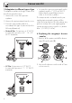
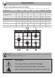
3. Replace the nozzles according to the
type of gas to be used and the
description in section 3.2 “Burner and
nozzle characteristics table”.
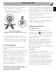
Ultra-rapid Dual burner
(A) Internal crown - (B) External crown
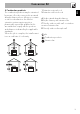
4. Put the burners back in their correct
position. Make sure that the holes of the
flame-spreader crowns are aligned with
the thermocouples (3) and igniters (4).
5 Test the appliance
Follow these instructions to leak test the
appliance:
Use a brush and liquid detergent to test all
gas connections for leaks. Bubbles around
connections indicate a leak. If a leak
appears, shut off the gas valve controls and
adjust the connections. Then check the
connections again. Remove all the
detergent product from the range. Replace
the parts on the burner and turn the knobs
on the gas tap valves.
NEVER TEST FOR GAS LEAKS WITH A
MATCH OR OTHER FLAMES.
Check that the flame at the maximum flame
position has a blue color. It should be clean
and soft in character. No blowing or lifting
of flame should occur. Occasional orange
flashes are normal and reflect different
elements in the air or gas.
Wipe away all the detergent product from
the range.
Replace the parts on the burner and turn the
knobs on the gas tap valves.
6 Minimum adjustment
For natural Gas:
Light the burner and turn the knob to the
minimum position . Remove the gas tap
knob and turn the adjustment screw at the
side of the tap rod until the desired minimum
flame is achieved.
Refit the knob and verify that the burner
flame is stable (when turning the knob
rapidly from the maximum to the minimum
position the flame must not go out).
Repeat this operation on the remaining gas
taps on the cooktop.
For LP Gas:
Turn off the burners and unplug the
appliance from the electrical power supply.
For regulating the minimum with LP, the
screws at the side of the tap rod must be
turned clockwise all the way. Once the
regulation has been completed, replace the
seal on the by-passes using paint or similar
materials. Follow the instructions given in
point 9 to locate the adjustment screws.