Contents 1.1 1.2 1.3 1.4 1.5 1.6 1.7 1.8 General safety instructions Identification plate Manufacturer’s liability Appliance purpose This user manual Disposal How to read the user manual To save energy 2 Description 2.1 Hob 2.2 Control panel 2.3 Other parts 3 Use 4 Cleaning and maintenance Cleaning the appliance Removing the doors Cleaning the door glazing Cleaning the inside of the ovens Pyrolytic cycle (pyrolytic oven) Extraordinary maintenance 5 Installation 5.1 5.2 5.3 5.4 5.
Instructions 1 Instructions 1.1 General safety instructions Risk of personal injury • During use the appliance and its accessible parts become very hot. Never touch the heating elements during use. • Protect your hands by wearing oven gloves when moving food inside the oven. • Never try to put out a fire or flames with water: Turn off the appliance and smother the flames with a fire blanket or other appropriate cover.
• Do not place metal objects, such as dishes or cutlery, on the hob surface during use as they may overheat. • Do not insert pointed metal objects (cutlery or utensils) into the slots in the appliance. • Do not pour water directly onto very hot trays. • Keep the oven door closed during cooking. • If you need to move food or at the end of cooking, open the door 5 cm for a few seconds, let the steam come out, then open it fully.
Instructions Risk of damaging the appliance • Use wooden or plastic utensils. • Racks and trays should be inserted as far as they will go into the side guides. The mechanical safety locks that prevent them from being removed must face downwards and towards the back of the oven cavity. • Do not sit on the appliance. • Do not use steam jets to clean the appliance. • Do not obstruct ventilation openings and heat dispersal slots.
• Take care not to spill acid substances such as lemon juice or vinegar on the hob. • Do not put empty pans or frying pans on switched on cooking zones. • Do not use steam jets to clean the appliance. • Do not use rough or abrasive materials or sharp metal scrapers. • Do not use cleaning products containing chlorine, ammonia or bleach on parts made of steel or that have metallic surface finishes (e.g. anodizing, nickel- or chromium-plating). • Do not use abrasive or corrosive detergents (e.g.
Instructions • To avoid potential overheating, the appliance must not be installed behind a decorative door or a panel. • Have the gas connection performed by authorised technical personnel. • Installation using a hose must be carried out so that the length of the hose does not exceed 2 metres when fully extended for steel hoses. • The hoses should not come into contact with moving parts and should not be crushed in any way. • If required, use a pressure regulator that complies with current regulations.
• The maximum capacity of the evaporation tray is 250 ml. • Be very careful not to exceed the maximum capacity of the evaporation tray. 1.2 Identification plate The identification plate bears the technical data, serial number and brand name of the appliance. Do not remove the identification plate for any reason. 1.
Instructions • Deliver the appliance to the appropriate recycling centre for electrical and electronic equipment waste, or return it to the retailer when purchasing an equivalent product, on a one for one basis. Our appliances are packaged in non-polluting and recyclable materials. • Deliver the packing materials to the appropriate recycling centre. Plastic packaging Danger of suffocation • Do not leave the packaging or any part of it unattended. • Do not let children play with the plastic bags. 1.
Instructions EN 1.8 To save energy • Only preheat the appliance if the recipe requires you to do so. • Unless otherwise indicated on the package, defrost frozen foods before placing them in the oven. • When cooking several types of food it is recommended to cook the foods one after the other to make the best use of the already hot oven. • Use dark metal moulds: They help to absorb the heat better. • Remove all trays and racks which are not required during cooking.
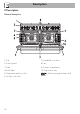
Description 2 Description General description 1 Hob 2 Control panel 3 Seals 4 Inside lights 5 Temperature probe socket 6 Pyrolytic oven door 78 7 Humidified oven door 8 Fans 9 Storage compartment 10 Evaporation tray Rack/tray support frame shelf
Description EN 2.1 Hob UR2 int. = Internal Ultra Rapid Burner crown UR2 ext. = External Ultra Rapid Burner crown SR = Semi-Rapid Burner R = Rapid Burner BBQ = Barbecue plate 1 = Front Induction cooking zone 2 = Rear Induction cooking zone Zone Dimensions (H x L - mm) Max. power draw (W)* Power draw in Booster function (W)* 1 2 201 x 197 201 x 197 1600 2100 1850 2300 Advantages of induction cooking The hob is equipped with an induction generator for each cooking zone.
Description 2.2 Control panel 1 Hob burner knobs 5 - 12 Programmer clock For lighting and adjusting the hob burners. Press and turn the knobs anti-clockwise to in order to light the relative burners. Turn the knobs to the zone between the maximum and minimum setting to adjust the flame. Return the knobs to the position to turn off the burners. For displaying the current time, setting programmed cooking and the minute minder timer.
Description Available accessories The indicator light comes on to indicate that the oven is heating up. It turns off as soon as it reaches the set temperature. It flashes regularly to indicate that the temperature set inside the oven is kept constant. Oven tray EN 10 Indicator light It is normal for the various temperature indicator lights to behave differently; it is not due to a fault. 2.3 Other parts Shelves The appliance features shelves to position trays and racks at different heights.
Description Tray rack Temperature probe (pyrolytic oven) With the temperature probe, you can cook according to the temperature measured at the centre the food. To be placed over the top of the oven tray; for cooking foods which may drip. Protective cover (pyrolytic oven) Rack Useful for supporting containers with food during cooking. Used to cover and protect the temperature probe socket when the temperature probe is not in use.
Use Instructions High temperature inside the oven during use Danger of burns • Keep the oven door closed during cooking. • Protect your hands wearing heat resistant gloves when moving food inside the oven. • Do not touch the heating elements inside the oven. • Do not pour water directly onto very hot trays. • Keep children under the age of 8 away from the appliance when it is in use.
Use Improper use Risk of damage to surfaces • Do not cover the bottom of the oven cavity with aluminium or tin foil sheets. • If you wish to use greaseproof paper, place it so that it will not interfere with the hot air circulation inside the oven. • Do not place pans or trays directly on the bottom of the oven cavity. • Do not use the open door to rest pans or trays on the internal glass pane. • Do not pour water directly onto very hot trays.
Racks and trays 3.3 Using the gas hob Racks and trays have to be inserted into the side guides until they come to a complete stop. • The mechanical safety locks that prevent the rack from being removed accidentally must face downwards and towards the back of the oven. All the appliance’s control and monitoring devices are located together on the front panel. The burner controlled by each knob is shown next to the knob. The appliance is equipped with an electronic ignition device.
Use Correct positioning of the flamespreader crowns and burner caps Before lighting the hob burners, make sure that the flame-spreader crowns are correctly positioned in their housings with their respective burner caps. Make sure that the holes in the flame-spreader crowns are aligned with the igniters and thermocouples (A). 3.4 Using the induction hot plates After use, turn off the hot plates used by returning the appropriate knob to the O position. Never rely solely on the cookware detector.
Use Cookware recognition When there is no saucepan on a cooking zone or if the saucepan is too small, no energy will be transmitted and the symbol will appear on the display. If there is a suitable saucepan on the cooking zone, the recognition system detects it and switches on the hob to the power level set using the knob. Energy transmission is also interrupted when the saucepan is removed from the cooking zone (the symbol will be shown on the display).
Use Limiting the cooking duration Power levels The hob has an automatic device which limits the duration of use. If the cooking zone settings are not changed, the maximum duration of operation for each zone depends on the power level selected. When the device for limiting the duration of use is activated, the cooking zone turns off, a short alert sounds and, if the zone is hot, the symbol appears on the display. The power in the cooking zone can be adjusted to various levels.
Use Each cooking zone is equipped with a heating accelerator that allows the maximum power to be delivered for a time that is proportional to the selected power. This function allows the selected power to be achieved in the shortest amount of time. 1. Turn the knob anticlockwise to position A and then release it. The display shows the symbol. Multizone function This function can be used to operate two cooking zones (front and rear) simultaneously when using pans like fish kettles or rectangular pans.
Use 3. Use the front cooking zone knob to set the required power level: this knob now controls both the cooking zones that are in use. To deactivate the Multizone function: • Put both knobs back to the 0 position (off). This function automatically divides the power equally between both zones that are in use. Controls lock The controls lock is a device that protects the appliance from accidental or inappropriate use. 1.
Use 3. Remove the heating element stop B and then lower the element so that the two reference marks rest on the edge of the hob. Pay attention not to fill above the edge of the tray. 4. Replace the plate on the hob. 5. Turn the barbecue heating element knob to a position between 1 and 9. The light turns on to indicate that the heating element is on. It is recommended you pre-heat the element for 5-6 minutes before placing food on it. 3.5 Using the ovens Switching on the ovens To switch on the ovens: 1.
Use The ECO function is recommended for cooking that does not require temperatures higher than 210°C. It is recommended that you select a different function for cooking at higher temperatures. Vapour Clean This function makes cleaning easier using the steam produced by a little quantity of water poured onto the appropriate groove placed on the bottom.
Fan with grill The air produced by the fan softens the strong heatwave generated by the grill, grilling perfectly even very thick foods. Perfect for large cuts of meat (e.g. shin of pork). Fan + lower element The combination of the fan with just the lower heating element allows cooking to be completed more rapidly. This system is recommended for sterilising or for finishing off the cooking of foods which are already well-cooked on the surface, but not inside, which therefore need a little more heat.
Use 3.6 Cooking with the Direct Steam function (humidified oven) Do not place food or any other object directly on the bottom of the oven. The base of the oven and the evaporation tray must always be left free. 1. Open the oven door. 2. Lift the cover of the evaporation tray. The maximum level is indicated by a mark on the inside of the tray. 3. Fill the tray with sufficient water for the cooking duration (see “Direct Steam cooking information table”).
End of Direct Steam cooking 1. Stand to the side of the appliance and open the door ajar for a few seconds to allow excess steam to escape. 2. Fully open the door when safe to do so and cautiously remove the food from the oven. 3. Wait for the appliance to cool down completely before cleaning it. 5. Use a sponge to remove any condensation from the base and walls of the oven cavity, the door glass and the drip tray at the front of the appliance.
Use 3.7 Using the temperature probe (pyrolytic oven) High temperature of the temperature probe Danger of burns • Do not touch the rod or the tip of the probe after having used it. • Wear oven gloves when handling the temperature probe. Improper use Risk of damage to surfaces • Take care not to scratch or damage enamelled or chrome-plated surfaces with the tip or the plug of the temperature probe. Improper use Risk of damage to the appliance • Do not insert the probe into openings and slots on the appliance.
Use Positioning the probe 1. Place the food on a tray. 2. Insert the tip of the probe into the food before placing it in the oven. 3. For best results, make sure that the temperature probe is placed transversely in the thickest part of the food and for least 3/4 of its length. Make sure that it does not touch the tray underneath and that it does not protrude from the food. Cooking using the temperature probe With preheating: 1. Set manual cooking (see “Using the ovens”). 2.
Use 4. Close the door. 5. Press the button for a few seconds; Press the button again. The default target temperature is indicated on the display and the symbol flashes. 6. Use the and buttons to regulate the target temperature to a value between the minimum and a maximum. • Minimum target temperature: corresponds to the instantaneous temperature measured by the probe plus 2°C. • Maximum target temperature: 99°C 7.
At the end of cooking 3.9 Cooking advice When the set target temperature for the temperature probe is reached, the heating elements are switched off and the appliance emits a series of beeps. 1. Press a button on the programmer clock to stop the buzzer. 2. Open the door. 3. Remove the probe from the food and unplug it from the socket. 4. Remove the food from the oven. 5. Make sure that the protective cover is properly closed. General advice 3.
Use Advice for cooking with the Grill and the Fan with grill • Meat can be grilled even when it is put into the cold oven or into the preheated oven if you wish to change the effect of the cooking. • With the Fan with grill function, we recommend that you preheat the oven before grilling. • We recommend placing the food at the centre of the rack. • With the Grill function, we recommend that you turn the temperature knob to the maximum value near the symbol to optimise cooking.
Use Setting the time When using the appliance for the first time or after a power failure, setting the time on one clock will set the same time on the other. If the time is not set, the oven will not switch on. Value decrease button Clock button Value increase button Ensure that the programmer clock shows the cooking duration symbol , otherwise it will not be possible to turn on the oven. Press the button to reset the programmer clock.
Use Timed cooking Timed cooking is the function which allows a cooking operation to be started and then ended after a specific length of time set by the user. 1. Keep the clock button the pressed until symbol appears. 2. Press the clock button the display the again. On symbol and the text appear, alternating with the current time. 3. Use the value increase and value decrease buttons to set the required minutes of cooking. 4. Select a function and a cooking temperature. 5. Wait approx.
4. Press the or button to set the required minutes. (for example 1 hour). 5. Press the menu button . The text will appear on the display in sequence with the pre-set cooking duration added to the current time (for example, the cooking end time shown is 18:30). 6. Press the or button to set the cooking end time. (for example, 19:30). Bear in mind that a few minutes for oven preheating must be added to the cooking time. 7. Wait approx.
Use Modifying the set data Minute minder timer The minute minder timer does not stop the cooking operation but rather informs the user when the set time has run out. The minute minder timer can be activated at any time. 1. Keep the clock button pressed for per a few seconds. The display shows the figures and the symbol flashing between the hours and minutes. 2. Use the value increase and value decrease buttons to set the number of minutes required. 3. Wait approx.
Use Cooking information table Function Shelf Temperature (°C) Time (minutes) Lasagne Pasta bake 3-4 3-4 Static Static 1 1 220 - 230 220 - 230 45 - 50 45 - 50 Veal roast Pork loin Sausages Roast beef Roast rabbit Turkey breast Roast pork neck Roast chicken 2 2 1.5 1 1.5 3 2-3 1.
Use Direct Steam cooking information table Food Lasagne Pasta bake Weight (Kg) Water (ml) Shelf Temperature (°C) Time (minutes) 1.6 120 - 130 2 190 - 200 35 - 40 1.2 - 1.5 120 - 130 2 190 - 200 35 - 40 MEAT Roast turkey 1.5 180 2 190 - 200 80 - 90 Pork loin Roast rabbit (pieces) Spare ribs (attached) Leg of lamb well done 1.5 180 2 190 - 200 85 - 90 1 160 2 180 - 190 80 - 90 0.5 160 2 200 55 - 60 2 160 2 190 - 200 95 - 100 100g ea.
Use Food Weight (Kg) Water (ml) Shelf Temperature (°C) Time (minutes) Roast potatoes Mixed roasted vegetables 1 80 2 210 - 220 40 - 45 0.6 80 2 210 35 Pasta Sliced roast meats/spare ribs Bread 0.3 100 - 110 2 120 15 - 25 0.5 100 - 110 2 120 15 - 25 0.5 100 - 110 2 120 15 - 25 Strudel 0.5 100 - 110 2 120 15 - 25 EN VEGETABLES REHEATING FOOD DESSERTS Bundt cake Strudel Muffins Paradise cake Sponge cake Biscuits (0.
Use Probe-cooking information table Type and cut of meat Target temperature (°C) Beef Roast beef: rare 50 - 53 Roast beef: medium 55 - 58 Roast beef: well done 65 - 70 Rib of beef: rare* 50 Rib of beef: medium* 58 Rib of beef: well done* 70 Pork Roast loin 80 - 85 Shoulder 80 - 85 Sausages** 75 - 80 Veal roast 75 - 80 Whole chicken 80 - 85 Whole turkey 80 - 85 Roast turkey (whole or breast) 80 - 85 Veal Poultry Lamb Leg of lamb with bone (rare) 65 Leg of lamb with bone (well d
4 Cleaning and maintenance 4.1 Cleaning the appliance Instructions To keep the surfaces in good condition, they should be cleaned regularly after use. Let them cool first. Improper use Risk of damage to surfaces • Do not use steam jets to clean the appliance. • Do not use cleaning products containing chlorine, ammonia or bleach on parts made of steel or that have metallic surface finishes (e.g. anodizing, nickelor chromium-plating). • Do not use abrasive or corrosive detergents (e.g.
Cleaning and maintenance Dirt which may have fallen on the hob while cleaning lettuce or potatoes can scratch the hob when moving pans. Consequently, remove any dirt from the cooking surface immediately. Changes in colour do not affect the operation and stability of the glass. These are not alterations to the material of the hob but just residues which have not been removed and have then carbonised.
4.2 Removing the doors For easier cleaning, the doors can be removed and placed on a tea towel or other protective sheet. To remove the door proceed as follows: 1. Open the door completely and insert two pins into the holes on the hinges indicated in the figure. 3. To reassemble the door, put the hinges in the relevant slots in the oven, making sure that grooved sections A are resting completely in the slots. Lower the door and once it is in place remove the pins from the holes in the hinges. 4.
Cleaning and maintenance 4.4 Cleaning the inside of the ovens Removing rack/tray support frames To keep the ovens in perfect condition, clean them regularly after allowing them to cool. • Take out all removable parts. Removing the guide frames enables the sides to be cleaned more easily. To remove the guide frames: Pull the frame towards the inside of the oven to release it from its groove A, then slide it out of the seats B at the back.
Vapour Clean (humidified oven) Vapor Clean is an assisted cleaning procedure which facilitates the removal of dirt. Thanks to this process, it is possible to clean the inside of the oven very easily. The dirt residues are softened by the heat and water vapour for easier removal afterwards. • Spray a water and washing up liquid solution inside the oven using a spray nozzle. Direct the spray against the side walls, upwards, downwards and towards the deflector.
Cleaning and maintenance End of the Vapor Clean cycle 4. Open the door and wipe away the less stubborn dirt with a microfibre cloth. 5. Use a non-scratch sponge with brass filaments on hard to remove deposits. 6. In case of grease residues use specific oven cleaning products. 7. Remove the water left inside the oven. For improved hygiene and to avoid food being affected by any unpleasant odours, we recommend that the oven is dried using a fan assisted function at 160°C for approximately 10 minutes.
Cleaning and maintenance It is recommended that you clean and dry the evaporation tray and the perforated cover after using the Direct Steam function. Common cleaning products can be used: avoid using products that are too harsh and/or acidic. The cover and the tray can be washed in a dishwasher. If limescale forms, use a limescale remover for steel surfaces.
Cleaning and maintenance Deactivating the door lock lever manually (pyrolytic oven) 1. Move the door lock lever to the right until it stops. Improper use Danger of burns • The following operations must always be performed with the appliance cold and switched off. • Never attempt to manually deactivate the door lock lever during a pyrolytic cycle. The door lock lever is located in the first slot on the left under the control panel, in the upper part of the front of the oven. (view from above) 2.
Cleaning and maintenance Pyrolytic cleaning is an automatic, high-temperature cleaning procedure that causes dirt to dissolve. Thanks to this process, it is possible to clean the inside of the oven very easily. Improper use Risk of damage to surfaces • Remove any food residues or large spills from previous cooking operations from the inside of the oven. • When this function is in use, the surfaces could reach temperatures that are higher than usual. • Keep children at a safe distance.
Cleaning and maintenance 6. At the end of the pyrolytic cycle, all the numbers on the display will flash and a buzzer will sound to indicate the end of the automatic cleaning cycle. 7. Move the function knob back to the “0” position. 8. The door remains locked as long as the temperature inside the oven returns to safety levels. 9. Wait for the oven to cool down and collect the residues deposited inside with a damp microfibre cloth.
Cleaning and maintenance 4.6 Extraordinary maintenance 4. Slide out and remove the light bulb. EN Live parts Danger of electrocution • Unplug the oven. • Use protective gloves. 1. Completely remove all accessories from inside the oven. 2. Remove the rack/tray support frames. 3. Remove the bulb cover using a tool (e.g. a screwdriver). Pay attention not to scratch the oven cavity enamel. Do not touch the halogen light bulb directly with your fingers, but wrap it in insulating material. 5.
Cleaning and maintenance Removing and installing the seal (humidified oven) To remove the seal: To permit thorough cleaning of the auxiliary oven, the door seal can be removed. There are fasteners in the 4 corners and in the centre to attach it to the edge of the oven. • Pull the seal outwards at all points in order to detach the fasteners. To keep the door seals clean, use a nonabrasive sponge and lukewarm water. Seals should be soft and elastic.
Installation 5.1 Gas connection Gas leak Danger of explosion • After carrying out any operation, check that the tightening torque of gas connections is between 10 Nm and 15 Nm. • If required, use a pressure regulator that complies with current regulations. • At the end of the installation, check for any leaks with a soapy solution, never with a flame. • Installation using a hose must be carried out so that the length of the hose does not exceed 2 metres when fully extended for steel hoses.
Installation Connection with a steel hose with bayonet fitting Carry out the connection to the gas mains using a steel hose with bayonet fitting compliant with B.S. 669. Apply insulating material to the thread of the gas hose connector 4 and then tighten the adapter 3. Screw the assembly to the movable connector 1 of the appliance, placing the seal supplied 2 between them.
Extraction of the combustion products This domestic appliance is not connected to a device for extracting combustion products. It must be installed and connected in accordance with current installation regulations. Pay particular attention to the relevant requirements regarding ventilation. The combustion products may be extracted by means of hoods connected to a natural draught chimney whose efficiency is certain or via forced extraction.
Installation Adjusting the minimum setting for LPG Tighten the screw located at the side of the cock spindle clockwise all the way. Following adjustment to a gas other than the one originally set in the factory, replace the gas setting label on the appliance with the one corresponding to the new gas. The label is inserted inside the nozzle pack (where present). 3. Replace the burners in their respective housings.
Installation Gas types and Countries 1 Natural Gas G20 G20 20 mbar G20/25 20/25 mbar 2 Natural Gas G20 G20 25 mbar 3 Natural Gas G25 G25 25 mbar G25.3 25 mbar 4 Natural Gas G25.1 G25.1 25 mbar 5 Natural Gas G25 G25 20 mbar 6 Natural Gas G2.350 G2.
Installation Burner and nozzle characteristics tables 1 Natural gas G20 - 20 mbar SR R UR2 int. UR2 ext. Rated heating capacity (kW) 1.80 3.0 0.9 3.30 97 120 70 128 Nozzle diameter (1/100 mm) Pre-chamber (printed on nozzle) Z H9 H1 F3 2 Natural gas G20 - 25 mbar 500 SR 800 R 400 UR2 int. 1200 UR2 ext. Rated heating capacity (kW) 0.8 3.4 Reduced flow rate (W) 1.80 3.
Installation SR R UR2 int. UR2 ext. 1.80 3.0 0.90 3.30 65 85 44 91 - - - - Reduced flow rate (W) 500 800 400 1300 Rated flow rate G30 (g/h) 131 218 65 240 Rated flow rate G31 (g/h) 8 LPG G30/31 - 37 mbar 129 SR 214 R 64 UR2 int. 236 UR2 ext. Rated heating capacity (kW) 1.90 3.0 0.80 3.
Installation 5.3 Positioning Heavy appliance Crushing hazard • Position the appliance into the cabinet cut-out with the help of a second person. Pressure on the open door Risk of damage to the appliance Any wall units installed above the appliance’s worktop must be positioned at least Y mm from it. If a hood is installed above the hob, refer to the hood instruction manual to ensure the correct clearance is left.
Installation EN Appliance overall dimensions B - Class 2 subclass 1 (Built-in appliance) 1 A 1200 mm B 600 mm C1 D min. 300 mm H 750 mm I 450 mm L2 800 mm 900 mm Minimum distance from side walls or other flammable material. 2 Minimum cabinet width (=A) *If a hood is installed above the hob, refer to the hood instructions manual to ensure that the correct clearance is left.
Installation Appliance dimensions: position of gas and electrical connections Position of gas and electrical connections (measurements given in mm). A B (max) B (min) C D E F (min) F (max) G = gas connection H = electrical connection 130 56 770 744 135 55 1200 894 920 Positioning and levelling the appliance After making the electrical and/or gas connections, properly level the appliance on the floor to ensure better stability.
Installation 3. Align the holes on the back of the side plinths with those on the base of the appliance. EN 2. Align the front plinth with the corresponding holes on the appliance. 4. Fasten the side plinth using a screw. 3. Fasten the front plinth using the screws that were previously removed. Installing the side plinth After having installed the front plinth, you should also install the side plinths. 1. Position the side plinths at the side of the front plinth. 2.
Installation Assembling the upstand The upstand provided is an integral part of the product. It must be fastened to the appliance prior to installation. The upstand must always be positioned and secured correctly on the appliance. 1. Position the upstand on the hob, and align the screw holes. 2. Secure the upstand to the hob using the fixing screws. 5.4 Electrical connection Power voltage Danger of electrocution • Have the electrical connection performed by authorised technical personnel.
Installation Accessing the terminal board To connect the power supply cable, you must access the terminal board on the rear casing: 1. Remove the screws fastening the plate to the rear casing. 3 x 6 mm² three-core cable. • 380-415 V 2N~ 4 x 2.5 mm² four-core cable. • 380-415 V 3N~ 2. Gently rotate the plate and remove it from its seat. 5 x 2.5 mm² five-core cable. The values indicated refer to the cross-section of the internal conductor.
Installation 5.5 Instructions for the installer It is recommended to slacken off the cable clamp screw before installing the power supply cable. 4. When finished, replace the plate on the rear casing and secure it in place using the screws that were previously removed. Fixed connection Fit the power line with an all-pole circuit breaker with a contact separation distance sufficient to provide complete disconnection in category III overvoltage conditions, pursuant to installation regulations.