Contents 1.1 1.2 1.3 1.4 1.5 1.6 1.7 1.8 General safety instructions Manufacturer’s liability Appliance purpose Identification plate This user manual Disposal How to read the user manual To save energy 2 Description 2.1 2.2 2.3 2.4 2.5 General Description Cooking hob Control panel Other parts Available accessories 3 Use 3.1 3.2 3.3 3.4 3.5 3.6 3.7 Cleaning the hob Cleaning the door Cleaning the oven cavity Vapor Clean Extraordinary maintenance 5 Installation 5.1 5.2 5.3 5.4 5.
Instructions 1 Instructions 1.1 General safety instructions RISK OF INJURY • Protect your hands by wearing oven gloves when moving food inside the oven. • Never try to put out a fire or flames with water: turn off the appliance and smother the flames with a fire blanket or other appropriate cover.
• While cooking do not place metal objects, such as cutlery or dishes on the hob surface as they may overheat. • Do not insert pointed metal objects (cutlery or utensils) into the slots in the appliance. • Do not pour water directly onto very hot trays. • Keep the oven door closed during cooking. • If you need to move food or at the end of cooking, open the door 5 cm for a few seconds, let the steam come out, then open it fully.
Instructions RISK OF DAMAGING THE APPLIANCE • Use wooden or plastic utensils. • Racks and trays should be inserted as far as they will go into the side guides. The mechanical safety locks that prevent them from being removed must face downwards and towards the back of the oven cavity. • Do not sit on the appliance. • Do not use steam jets to clean the appliance. • Do not obstruct ventilation openings and heat dispersal slots.
• All pans must have smooth, flat bottoms. • If any liquid does boil over or spill, remove the excess from the hob. • Take care not to spill acid substances such as lemon juice or vinegar on the hob. • Do not put empty pans or frying pans on switched on cooking zones. • Do not use steam jets to clean the appliance. • Do not use rough or abrasive materials or sharp metal scrapers.
Instructions Installation and maintenance • THIS APPLIANCE MUST NOT BE INSTALLED IN A BOAT OR CARAVAN. • The appliance must not be installed on a pedestal. • Position the appliance into the cabinet cut-out with the help of a second person. • To prevent any possible overheating, the appliance should not be installed behind a decoration door or a panel. • Have the gas connection performed by authorised staff.
• This appliance is not connected to an exhaust system for combustion products. It must be installed and connected in compliance with the current installation regulations. Special attention should be paid to the relevant requirements as for ventilation. For this appliance • Ensure that the appliance is switched off before replacing the bulb. • Do not rest any weight or sit on the open door of the appliance. • Take care that no objects are stuck in the doors. 1.
Instructions 1.6 Disposal This appliance must be disposed of separately from other waste (Directives 2002/95/EC, 2002/96/EC, 2003/108/EC). The appliance does not contain substances in quantities sufficient to be considered hazardous to health and the environment, in accordance with current European directives. To dispose of the appliance: • Cut the power supply cable and remove it along with the plug. Power voltage Danger of electrocution • Disconnect the mains power supply. • Unplug the appliance.
1.7 How to read the user manual 1.8 To save energy This user manual uses the following reading conventions: • Only preheat the appliance if the recipe requires you to do so. • Unless otherwise indicated on the package, defrost frozen foods before placing them in the oven. • When cooking several types of food it is recommended to cook the foods one after the other to make the best use of the already hot oven. • Use dark metal moulds: They help to absorb the heat better.
Description 2 Description 2.
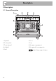
Description EN 2.2 Cooking hob AUX = Auxiliary burner SR = Semi-rapid burner R = Rapid burner UR2 int. = Ultra rapid burner with internal crown UR2 ext. = external crown ultra rapid burner 2.3 Control panel 1 Hob burner knobs For lighting and adjusting the hob burners. Press and turn the knobs anti-clockwise to in order to light the relative burners. Turn the knobs to the zone between the maximum and minimum setting to adjust the flame. Return the knobs to the position off the burners.
Description 3 Temperature knob Interior lighting This knob allows you to select the cooking temperature. Turn the knob clockwise to the required value, between the minimum and maximum setting. The appliance’s interior lighting comes on: • when the door is opened; • When any function is selected, apart from the function. 4 Programmer clock For displaying the current time, setting programmed cooking operations and the minute minder timer.
Description 2.5 Available accessories Deep tray EN Rack Used for supporting containers with food during cooking. Useful for collecting fat from foods placed on the rack above and for cooking pies, pizzas and baked desserts. Temperature sensor Tray The temperature sensor enables cooking controlled by the temperature measured at the centre of the food. Useful for collecting fat from foods placed on the rack above and for cooking sweets, biscuits, etc.
Description Protective cover Ring reducer Useful when using small cookware. Not all accessories are available on some models. Used to close and protect the temperature sensor socket when the latter is not in use. Self-cleaning panels Useful for absorbing small grease residues. 72 The oven accessories intended to come into contact with food are made of materials that comply with the provisions of current legislation.
Use Instructions High temperature inside the oven during use Danger of burns • Keep the oven door closed during cooking. • Protect your hands wearing heat resistant gloves when moving food inside the oven. • Do not touch the heating elements inside the oven. • Do not pour water directly onto very hot trays. • Keep children under the age of 8 away from the oven when it is in use.
Use High temperature inside the storage compartment Danger of fire or explosion • Do not spray any spray product near the appliance. • Do not use or leave flammable materials near the appliance or the storage compartment. • Do not use plastic cookware or containers for cooking. • Do not place sealed tins or containers in the oven cavity. • Do not leave the appliance unattended during cooking operations where fats and oils could be released. • Remove all trays and racks which are not required during cooking.
3.1 Using the accessories 3.2 Using the hob Ring reducers All the appliance’s control and monitoring devices are located together on the front panel. The burner controlled by each knob is shown next to the knob. The appliance is equipped with an electronic ignition device. Simply press the knob and turn it anticlockwise to the maximum flame symbol, until the burner ignites. If the burner does not light in the first 15 seconds, turn the knob to and wait 60 seconds before trying again.
Use Correct positioning of the flamespreader crowns and burner caps Before lighting the hob burners, make sure that the flame-spreader crowns are correctly positioned in their housings with their respective burner caps. Make sure that the holes 1 of the flame-spreader crowns are aligned with the thermocouples 2 and igniters 3. 3.3 Using the storage compartment There is a storage compartment located at the bottom of the cooker; this can be used to store pans or metal objects required for its use. 1.
Use Switching on the oven To switch on the oven: 1. Select the cooking function using the function knob. 2. Select the temperature using the temperature knob. Ensure that the programmer clock shows the cooking duration symbol , otherwise it will not be possible to turn on the oven. Press the key to reset the programmer clock. Functions list Static As the heat comes from above and below at the same time, this system is particularly suitable for certain types of food.
Use Grill The heat coming from the grill element gives perfect grilling results above all for thin and medium thickness meat and, in combination with the rotisserie (where fitted), gives the food an even browning at the end of cooking. Perfect for sausages, spare ribs and bacon. This function enables large quantities of food, particularly meat, to be grilled evenly. Fan-assisted grill The air produced by the fan softens the strong heatwave generated by the grill, grilling perfectly even very thick foods.
Use Eco ECO cooking: this function is particularly suitable for cooking on a single shelf with low energy consumption. It is recommended for all types of food, excluding those that can create a lot of humidity (such as vegetables). To obtain maximum energy savings and reduce cooking times, it is recommended to place food in the oven without preheating. When using the ECO function, avoid opening the door during cooking. Cooking times are longer with the ECO function. EN 3.
Use Timed cooking Setting the time If the time is not set, the oven will not switch on. On the first use, or after a power failure, the digits will be flashing on the appliance’s display. 1. Hold down the clock key for two seconds. The dot between the hours and the minutes flashes. 2. The time can be set via the value increase key and value decrease key . Keep the key pressed in to increase or decrease rapidly. 3. Wait 7 seconds. The dot between the hours and the minutes stops flashing. 4.
Use 6. Press the clock key programmer clock. to reset the Programmed cooking Programmed cooking is the function which allows a cooking operation to be started at a set time and then ended after a specific length of time set by the user. 1. Set the cooking time as described in the previous point “Timed cooking”. You cannot set cooking times in excess of 10 hours. 2. Hold the menu key 2 seconds. down for To cancel the set programming press and hold down the value increase and the value 3.
Use 6. Press the or key to set the cooking end time. (for example, 19:30). Bear in mind that a few minutes for oven preheating must be added to the cooking time. 7. Wait approx. 7 seconds without pressing any key in order for the function to activate. The current time will appear on the display, and the symbols and will turn off while the indicator light comes on. 8. Select a cooking temperature and function. 9. At the end of cooking the heating elements will be deactivated.
Use Modifying the set data The minute minder timer does not stop the cooking operation but rather informs the user when the set time has run out. The minute minder timer can be activated at any time. 1. Keep the clock key pressed for per a few seconds. The display shows the figures and the symbol flashing between the hours and minutes. 2. Use the value increase and value decrease keys to set the number of minutes required. 3. Wait approx.
Use 3.6 Using the temperature probe High temperature of the temperature probe Danger of burns • Do not touch the rod or the tip of the probe after use. • Protect your hands with heat-resistant gloves when using the probe. Improper use Risk of damage to surfaces • Take care not to scratch or damage enamelled or chrome-plated surfaces with the tip or the plug of the temperature probe. Improper use Risk of damage to the appliance • Do not insert the probe into openings and slots on the appliance.
Use 1. Place the food on a tray. 2. Insert the tip of the probe into the food before you place it in the oven. 3. For best results, make sure that the temperature probe is placed transversely in the thickest part of the food and for least 3/4 of its length. Make sure that it does not touch the tray underneath and that it does not protrude from the food. Setting the cooking cycle when using the temperature probe With preheating: 1. Set a manual cooking cycle (see “Switching on the oven”). 2.
Use 4. Close the door. 5. Press the key for a few seconds; Now press the key again. The display will show the default target temperature with the symbol flashing. 6. Use the and keys to set the minimum and maximum target temperature values. • Minimum target temperature: the momentary probe temperature plus 2 °C. • Maximum target temperature: 99 °C 7. Wait a few seconds or press the key to display the momentary probe temperature.
Use temperature, and use the and keys to adjust it while cooking is in progress. 2. Press again or wait 5 seconds to return to cooking mode. At the end of cooking When the temperature probe's target temperature is reached, the heating elements are switched off and the appliance emits a series of beeps. 1. Press a programmer clock key to silence the buzzer. 2. Open the door. 3. Remove the probe from the food and unplug it from the socket. 4. Remove the food from the oven. 5.
Use • With the Grill function, we recommend that you turn the temperature knob to the maximum value near the symbol to optimise cooking. • Foods should be seasoned before cooking. Foods should also be coated with oil or melted butter before cooking. • Use the oven tray on the first bottom shelf to collect liquids produced by grilling. Low temperature cooking with the temperature probe • This kind of cooking is recommended for tender and lean meats which should not exceed a core temperature of 65 °C.
Use Cooking information table Function Shelf Temperature (°C) Time (minutes) Lasagne Pasta bake 3-4 3-4 Static Static 1 1 220 - 230 220 - 230 45 - 50 45 - 50 Roasted veal Pork loin Sausages Roast beef Roast rabbit Turkey breast Roast pork neck Roast chicken 2 2 1.5 1 1.5 3 2-3 1.2 Round Round Fan-assisted grill Round Round Round Round Round 2 2 4 2 2 2 2 2 180 - 190 180 - 190 260 200 180 - 190 180 - 190 180 - 190 180 - 190 Pork chops Spare ribs Bacon Pork fillet Beef fillet 1.5 1.5 0.7 1.
Use Illustrative table of temperature probe cooking cycle settings Type and cut of meat Temperature target (°C) Beef Roast beef: rare Roast beef: medium Roast beef: well done Ribs: rare* Ribs: medium* Ribs: well done* 50 - 53 55 - 58 65 - 70 50 58 70 Roast pork loin Shoulder Sausages** 80 - 85 80 - 85 75 - 80 Roasted veal 75 - 80 Whole chicken Whole turkey Turkey roast (whole or breast) 80 - 85 80 - 85 80 - 85 Pork Veal Poultry Lamb Leg of lamb with bone (rare) 65 Leg of lamb with bone (well don
Cleaning and maintenance Instructions Improper use Risk of damage to surfaces • Do not use steam jets to clean the appliance. • Do not use cleaning products containing chlorine, ammonia or bleach on parts made of steel or that have metallic surface finishes (e.g. anodizing, nickelor chromium-plating). • Do not use abrasive or corrosive detergents (e.g. scouring powders, stain removers and metallic sponges) on glass parts. • Do not use rough or abrasive materials or sharp metal scrapers.
Cleaning and maintenance 4.1 Cleaning the hob Igniters and thermocouples Cooking hob grids For correct operation the igniters and thermocouples must always be perfectly clean. Check them frequently and clean them with a damp cloth if necessary. Remove any dry residues with a wooden toothpick or a needle. Remove the grids and clean them in lukewarm water and non-abrasive detergent. Make sure to remove any encrustations. Dry them thoroughly and return them to the hob.
4.2 Cleaning the door Removing the door For easier cleaning it is recommended to remove the door and place it on a tea towel. To remove the door proceed as follows: 1. Open the door completely and insert two pins into the holes on the hinges indicated in the figure. 3. To reassemble the door, put the hinges in the relevant slots in the oven, making sure that grooved sections A are resting completely in the slots. Lower the door and once it is in place remove the pins from the holes in the hinges.
Cleaning and maintenance Removing the internal glass panes For easier cleaning the internal glass panes of the door can be removed. 1. Open the door. 2. Position the locking hooks in the hinge holes to prevent accidental closing of the door. 3. Remove the internal glazing pane by pulling the rear part gently upwards, following the movement indicated by the arrows (1). 5. Remove the intermediate glass pane by lifting it upwards. 6. Clean the external glass pane and the panes removed previously.
Cleaning and maintenance In order to keep your oven in the best possible condition, clean it regularly after letting it cool down. Avoid letting food residue dry inside the oven cavity, as this could damage the enamel. Take out all removable parts before cleaning. For easier cleaning, it is recommended to remove: • the door • The rack/tray support frames • The seal.
Cleaning and maintenance Removing the side self-cleaning panels and rack/tray support frames Removing the side self-cleaning panels and the rack/tray support frames enables the sides to be cleaned more easily. To remove the self-cleaning panels and rack/tray support frames: • Pull the frame towards the inside of the oven to unhook it from its groove A, then slide it out of the seats B at the back. The side self-cleaning panel is attached to the rack/tray support frame. 4.
Cleaning and maintenance Vapor Clean setting 1. Turn the function knob to the symbol and the temperature knob to the symbol EN • Pour approximately 40 cc of water into the tray. Make sure it does not overflow out of the cavity. . 2. Set a cooking time of 18 minutes using the programmer clock. The Vapor Clean cycle starts a few seconds after the last press on the programmer clock keys. 3.
Cleaning and maintenance End of the Vapor Clean cycle 4.5 Extraordinary maintenance 4. Open the door and wipe away the less stubborn dirt with a microfibre cloth. 5. Use an anti-scratch sponge with brass filaments on tougher encrustations. 6. In case of grease residues use specific oven cleaning products. 7. Remove the water left inside the oven.
Cleaning and maintenance Replacing the internal light bulb 4. Slide out and remove the light bulb. EN Live parts Danger of electrocution • Ensure that the appliance is switched off before replacing the bulb. The oven is fitted with a 40W light bulb. 1. Completely remove all accessories from inside the oven. 2. Remove the rack/tray support frames. 3. Use a tool (e.g. a spoon) to remove the bulb cover. Do not touch the halogen light bulb directly with your fingers, use an insulating material. 5.
Installation 5 Installation 5.1 Gas connection Gas leak Danger of explosion • After carrying out any operation, check that the tightening torque of gas connections is between 10 Nm and 15 Nm. • If required, use a pressure regulator that complies with current regulations. • At the end of the installation, check for any leaks with a soapy solution, never with a flame.
Installation Connection with a steel hose Make the connection to the gas mains using a continuous wall steel hose whose specifications comply with the applicable standard. Carefully screw the connector 3 to the gas connector 1 of the appliance, placing the seal 2 between them. Connection with a steel hose with bayonet fitting Connection using a rubber hose complying with current standards is only permitted if the hose can be inspected along its entire length.
Installation Connection to LPG Room ventilation Use a pressure regulator and make the connection on the gas cylinder following the guidelines set out in the standards in force. The appliance should be installed in rooms that have a permanent air supply in accordance with the standards in force. The room where the appliance is installed must have enough air flow for the regular combustion of gas and the necessary air change in the room itself.
Installation In case of operation with other types of gas, the burner nozzles must be changed and the minimum flame adjusted on the gas cocks. Replacing nozzles 1 Extraction using a hood 2 Extraction without a hood 1. Remove the grids, burner caps and flame-spreader crowns to access the burner cups. 2. Replace the nozzles using a 7 mm spanner according to the gas to be used (see Gas types and Countries).
Installation Adjusting the minimum setting for natural or town gas Light the burner and turn it to the minimum position. Extract the gas cock knob and turn the adjustment screw next to the tap rod (depending on the model) until the correct minimum flame is achieved. Refit the knob and verify that the burner flame is stable. Turn the knob rapidly from the maximum to the minimum setting: The flame should not go out. Repeat the operation on all gas cocks.
Installation Gas types and Countries Gas types IT GB-IE FR-BE DE AT NL ES PT SE RU DK PL HU 1 Natural gas G20 20 mbar • • • • • • • • • • EN G20 • G20/25 20/25 mbar 2 Natural gas G20 G20 • 25 mbar 3 Natural gas G25 G25 25 mbar G25.3 25 mbar • • 4 Natural gas G25.1 G25.1 • 25 mbar 5 Natural gas G25 G25 • 20 mbar 6 Natural gas G2.350 G2.
Installation Burner and nozzle characteristics tables 1 Natural gas G20 – 20 mbar AUX SR R UR2 int. UR2 ext. Rated heating capacity (kW) 1.0 1.8 3.0 0.9 4.1 Nozzle diameter (1/100 mm) 72 97 120 70 150 Pre-chamber (printed on nozzle) (X) (Z) (H9) (H1) (H3) 2 Natural gas G20 – 25 mbar 400 AUX 500 SR 800 R 400 UR2 int. 1200 UR2 ext. Rated heating capacity (kW) 1.1 1.8 3.0 0.9 4.
7 Liquid gas G30/31 - 30/37 mbar AUX SR R UR2 int. UR2 ext. Rated heating capacity (kW) 1.0 1.8 3.0 0.9 3.8 Nozzle diameter (1/100 mm) 50 65 85 44 96 - - - - - Reduced flow rate (W) 400 500 800 400 1300 Rated flow rate G30 (g/h) 73 131 218 65 298 Rated flow rate G31 (g/h) 8 LPG G30/31-37 mbar 71 AUX 129 SR 214 R 64 UR2 int. 293 UR2 ext. Rated heating capacity (kW) 1.1 1.9 3.0 0.8 3.
Installation 5.3 Positioning Heavy appliance Crushing hazard • Position the appliance into the cabinet cut-out with the help of a second person. Pressure on the open door Risk of damage to the appliance • Never use the oven door to lever the appliance into place when fitting. • Avoid exerting too much pressure on the door when open. Any wall units positioned above the worktop of the appliance must be at a minimum distance of at least Y mm.
Installation EN Appliance overall dimensions B - Class 2 subclass 1 (Built-in appliance) A 900 mm B 600 mm C1 D min. 150 mm 900 - 915 mm H 750 mm I 450 mm L2 900 mm 1 Minimum distance from side walls or other flammable material. 2 Minimum cabinet width (=A). C - Class 2 subclass 1 (Built-in appliance) The appliance must be installed by a qualified technician and according to the regulations in force.
Installation Dimensions of the appliance: locations of gas and electric connections (mm) Positioning and levelling Heavy appliance Risk of damage to the appliance • Insert the front feet first and then the rear ones. After making the electrical and/or gas connections, screw the four adjustable feet supplied with the appliance. A 124 B 38 C 42 D 634 F min 70 - max 110 H 809 L 898 E = Electrical connection G = Gas connection 110 The appliance must sit level on the floor to ensure stability.
Installation Fastening to the wall 3. Assemble the fastening bracket. EN The anti-tip devices must be installed in order to prevent the appliance from tipping over. 1. Screw the wall fastening plate to the rear of the appliance. 4. Align the base of the hook on the fastening bracket with the base of the slot on the wall fastening plate. 2. Adjust the height of the 4 feet.
Installation 5. Align the base of the fastening bracket with the ground and tighten the screws to fix the measurements. 6. Use 50 mm for the distance from the side of the appliance to the bracket holes. 112 7. Move the bracket onto the wall and mark the position of the holes to be drilled in the wall. 8. After drilling the holes in the wall, use wall plugs and screws to fasten the bracket to the wall. 9.
Installation The upstand provided is an integral part of the product; it must be fastened to the appliance prior to installation. The upstand must always be positioned and secured correctly on the appliance. 1. Loosen the 4 screws (A) on the back of the hob (2 for each side) using a screwdriver. 2. Place the upstand on the worktop. 3. Align the slots of the upstand (B) with the screws (A). 5.
Installation The appliance can work in the following modes: • 220-240 V 1N~ 3 x 1.5 mm² three-core cable. The values indicated above refer to the cross-section of the internal lead. The aforementioned power cables are sized taking into account the coincidence factor (in compliance with standard EN 60335-2-6). Fixed connection Fit the power line with an all-pole disconnection switch, with at least 3 mm between its contacts, in compliance with installation regulations.