
User manual

Installation
40
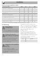
Burner and nozzle specifications tables
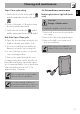
The nozzles not provided are available at Authorised Service Centres.
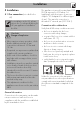
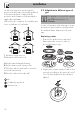
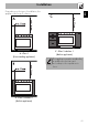
5.3 Positioning
This appliance may be installed next to
walls, one of which must be higher than the
worktop, at a minimum distance of X mm
from the side of the appliance, as shown in
figures “A” and “C” relative to the
installation classes.
Any wall units positioned above the
worktop of the appliance must be at a
minimum distance of at least Y mm. If a
hood is installed above the hob, refer to the
hood instruction manual to ensure the
correct clearance is left.
1 Natural gas G20 AUX SR R UR2
Rated heating capacity (kW)
1.0 1.8 3.0 4.2
Nozzle diameter (1/100 mm)
72 97 120 145
Pre-chamber (printed on nozzle)
(X) (Z) (H9) (F3)
Reduced flow rate (W)
400 500 800 1400
8 LPG G30/31 AUX SR R UR2
Rated heating capacity (kW)
1.0 1.80 3.0 4.0
Nozzle diameter (1/100 mm)
50 65 85 100
Pre-chamber (printed on nozzle)
--- -
Reduced flow rate (W)
400 500 800 1400
Rated flow rate G30 (g/h)
73 131 218 291
Rated flow rate G31 (g/h)
71 129 214 286
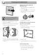
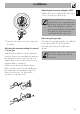
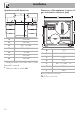
Heavy appliance
Crushing hazard
• Position the appliance into the cabinet
cut-out with the help of a second person.
Pressure on the open door
Risk of damage to the appliance
• Never use the oven door to lever the
appliance into place when fitting.
• Avoid exerting too much pressure on
the door when open.
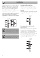
Heat production during appliance
operation
Risk of fire
• Veneers, adhesives or plastic
coatings on adjacent furniture should
be temperature-resistant (not less
than 90 °C).
X 150 mm
Y 750 mm