Table of contents 1.1 1.2 1.3 1.4 1.5 1.6 1.7 4 General safety instructions Manufacturer liability Appliance purpose Identification plate This user manual Disposal How to read the user manual 2 Description 2.1 2.2 2.3 2.4 2.5 General Description Cooking hob Control panel Other parts Available accessories Cleaning the surfaces Cleaning the hob Cleaning the door Cleaning the oven cavities Vapour Clean Extraordinary maintenance 5 Installation 5.1 5.2 5.3 5.4 5.
Instructions 1 Instructions 1.1 General safety instructions Risk of personal injury • During use the appliance and its accessible parts become very hot. Keep children well away from the appliance. • Protect your hands by wearing oven gloves when moving food inside the oven. • Never try to put out a fire or flames with water: turn off the appliance and smother the flames with a fire blanket or other appropriate cover.
• Keep the oven door closed during cooking. • If you need to move food or at the end of cooking, open the door 5 cm for a few seconds, let the steam come out, then open it fully. • Do not open the storage compartment (where present) when the oven is on and still hot. • The items inside the storage compartment could be very hot after using the oven. • Switch off the appliance after use. • Do not pull the cable to remove the plug.
Instructions • Do not sit on the appliance. • Racks and trays should be inserted as far as they will go into the side guides. The mechanical safety locks that prevent them from being removed must face downwards and towards the back of the oven. • Never leave the appliance unattended during cooking operations where fats or oils could overheat and take fire. Be very careful • Danger of fire: do not store items on the cooking surfaces. • Do not spray any spray products near the oven.
• Do not put empty pans or frying pans on switched on cooking zones. • Do not use rough or abrasive materials or sharp metal scrapers. • Do not use cleaning products containing chlorine, ammonia or bleach on parts made of steel or that have metallic surface finishes (e.g. anodizing, nickel- or chromium-plating). • Do not wash the removable components such as the hob grids, flame-spreader crowns and burner caps in a dishwasher. • Never use the oven door to lever the appliance into place when fitting.
Instructions • The hoses should not come into contact with moving parts and should not be crushed in any way. • If required, use a pressure regulator that complies with current regulations. • After carrying out any operation, check that the tightening torque of gas connections is between 10 Nm and 15 Nm. • At the end of the installation, check for any leaks with a soapy solution, never with a flame. • Have the electrical connection performed by authorised technicians.
1.4 Identification plate The identification plate bears the technical data, serial number and brand name of the appliance. Do not remove the identification plate for any reason. To dispose of the appliance: • Cut the power supply cable and remove it along with the plug. 1.5 This user manual This user manual is an integral part of the appliance and must therefore be kept in its entirety and within the user’s reach for the whole working life of the appliance.
Instructions 1.7 How to read the user manual This user manual uses the following reading conventions: Instructions General information on this user manual, on safety and final disposal. Description Description of the appliance and its accessories. Use Information on the use of the appliance and its accessories. Cleaning and maintenance Information for proper cleaning and maintenance of the appliance. Installation Information for the qualified technician: Installation, operation and inspection.
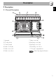
Description EN 2 Description 2.
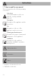
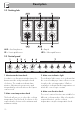
Description 2.2 Cooking hob AUX = Auxiliary burner SR = Semi-rapid burner R = Rapid UR2 = Ultra-rapid burner 2.3 Control panel 1 Minute minder timer knob 3 Main oven indicator light In order to use the minute minder timer, the buzzer must be set by turning the knob clockwise. The numbers indicated are minutes. Adjustment is progressive and intermediate positions between the figures can be used. The indicator light comes on to indicate that the oven is heating up.
Description It turns on the light inside the oven or starts the grill and lower heating elements to a temperature ranging from a minimum of 50 °C to a maximum of 245 °C. At the maximum temperature it is also possible to select some functions optimised for specific cooking types. 2.4 Other parts EN 5 Auxiliary oven temperature/function knob Shelves The appliance features shelves to position trays and racks at different heights. The insertion heights are indicated from the bottom upwards (see 2.
Description Interior lighting Ring reducer The appliance’s interior lighting comes on: (main oven) • when the door is opened; • when any function is selected, apart from the function. Useful when using small cookware. Deep tray when the door is open, it is not possible to turn off the interior lighting. (auxiliary oven) • when the auxiliary oven temperature/ function knob is turned to the symbol or to any function. 2.5 Available accessories Not all accessories are available on some models.
Description Rack To be placed over the top of the tray; for cooking foods which may drip. Useful for supporting containers with food during cooking.
Use 3 Use High temperature inside the oven during use Danger of burns • Keep the oven door closed during cooking. • Protect your hands wearing heat resistant gloves when moving food inside the oven. • Do not touch the heating elements inside the oven. • Do not pour water directly on very hot trays. • Keep children under the age of 8 away from the oven when it is in use. • If you need to move food or at the end of cooking, open the door 5 cm for a few seconds, let the steam come out, then open it fully.
High temperature inside the storage compartment Danger of fire or explosion • Do not spray any spray product near the appliance. • Do not use or leave flammable materials near the appliance or the storage compartment. • Do not use plastic cookware or containers for cooking. • Do not place sealed tins or containers in the oven cavity. • Do not leave the appliance unattended during cooking operations where fats and oils could be released. • Remove all trays and racks which are not required during cooking.
Use 3.1 To save energy 3.2 Using the accessories • Preheat the appliance only if the recipe requires it. • Unless differently stated on the package, defrost frozen food before placing it in the cooking compartment. • In case of multiple cooking, it is recommended to cook food one after the other to exploit the already hot cooking compartment. • Use dark metal moulds: They help to absorb the heat better. • Remove all trays and racks which are not required during cooking.
Racks and trays 3.3 Using the hob Racks and trays have to be inserted into the side guides until they come to a complete stop. • The mechanical safety locks that prevent the rack from being taken out accidentally have to face downwards and towards the oven back. All the appliance’s control and monitoring devices are located together on the front panel. The burner controlled by each knob is shown next to the knob. The appliance is equipped with an electronic ignition device.
Use Correct positioning of the flame-spreader crowns and burner caps Before lighting the hob burners, make sure that the flame-spreader crowns are correctly positioned in their seats with their respective burner caps. Make sure that the holes 1 in the flame-spreader crowns are aligned with the igniters 3 and thermocouples 2.
3.5 Using the ovens Switching on the main oven 1. Select manual cooking or set the cooking duration using the timer knob. Adjustment is progressive so that the time can also be set to any intermediate value between these numbers. 2. Select the temperature using the temperature knob. 3. Select the cooking function using the function knob. At the end of timed cooking, a buzzer sounds that stops automatically after a few seconds.
Use Fan with round heating element The combination of the fan and the round heating element (incorporated in the rear of the oven) allows you to cook different foods on several levels, as long as they need the same temperatures and same type of cooking. Hot air circulation ensures instant and even distribution of heat. It will be possible, for instance, to cook fish, vegetables and biscuits simultaneously (on different levels) without odours and flavours mingling.
Switching on the auxiliary oven Turn the temperature/function knob to the required temperature, from a minimum of 50°C to a maximum of 245°C, or to the required function (at the maximum temperature). Auxiliary oven functions Light bulb Turns on the light inside the oven cavity. Static (min 50 °C - max 245 °C) As the heat comes from above and below at the same time, this system is particularly suitable for certain types of food.
Use Advice for cooking with the Grill Advice for defrosting and proving • Meat can be grilled even when it is put into the cold oven or into the preheated oven if you wish to change the effect of the cooking. • When using the Fan with grill function, we recommend that you preheat the oven before grilling. • We recommend placing the food at the centre of the rack. • With the Grill function, we recommend that you turn the temperature knob to the maximum value to optimise cooking.
Use EN Main oven cooking information table Weight (kg) Function Shelf Temperature (°C) Lasagne Pasta bake 3-4 3-4 Static Static 1 1 220 - 230 220 - 230 45 - 50 45 - 50 Roasted veal Pork loin Sausages Roast beef Roast rabbit Turkey breast Roast pork neck Roast chicken 2 2 1.5 1 1.5 3 2-3 1.
Use Auxiliary oven cooking information table Weight (kg) Function Shelf Temperature (°C) Roast rabbit Roast chicken 1 1 Static Static 2 2 190 - 200 190 - 200 Chops Hamburgers Pork sausages Pork spare ribs Bacon 0.8 0.6 0.6 0.7 0.6 Grill Grill Grill Grill Grill 4 4 4 4 4 250 250 250 250 250 Food Time (minutes) 85 - 90 80 - 85 1nd surface 2nd surface 13 5 7 3 15 30 - 35 10 3 The times indicated in the table do not include preheating times and are provided only as a guide.
4 Cleaning and maintenance Improper use Risk of damage to surfaces • Do not use steam jets to clean the appliance. • Do not use cleaning products containing chlorine, ammonia or bleach on parts made of steel or that have metallic surface finishes (e.g. anodizing, nickelor chromium-plating). • Do not use abrasive or corrosive detergents (e.g. scouring powders, stain removers and metallic sponges) on glass parts. • Do not use rough or abrasive materials or sharp metal scrapers.
Cleaning and maintenance 4.2 Cleaning the hob Igniters and thermocouples Cooking hob grids For correct operation the igniters and thermocouples must always be perfectly clean. Check them frequently and clean them with a damp cloth if necessary. Remove any dry residues with a wooden toothpick or a needle. Remove the grids and clean them in lukewarm water and non-abrasive detergent. Make sure to remove any encrustations. Dry them thoroughly and return them to the hob.
4.3 Cleaning the door Removing the door For easier cleaning, the door can be removed and placed on a towel. To remove the door proceed as follows: 1. Open the door completely and insert two pins into the holes on the hinges indicated in the figure. 3. To reassemble the door, put the hinges in the relevant slots in the oven, making sure that grooved sections A are resting completely in the slots. Lower the door and once it is in position, remove the pins from the holes in the hinges.
Cleaning and maintenance Removing the internal glass panes For easier cleaning, the internal glass panes of the door can be removed. 1. Remove the internal glass pane by pulling the rear part gently upwards following the movement indicated by the arrows (1). This way, the 4 pins attached to the glass detach from their housings in the door. 2. Then, pull the front part upwards (2). 3. Remove the intermediate glazing pane by lifting it upwards.
4.4 Cleaning the oven cavities Removing racks/trays support frames For the best oven cavities upkeep, clean them regularly after having allowed them to cool. Avoid letting food residue dry inside the oven cavities, as this could damage the enamel. Take out all removable parts. Removing the guide frames enables the sides to be cleaned more easily. This operation should be performed each time the automatic cleaning cycle is used (on some models only). To remove the guide frames.
Cleaning and maintenance 4.5 Vapour Clean Vapor Clean is an assisted cleaning procedure which facilitates the removal of dirt. Thanks to this process, it is possible to clean the inside of the main oven very easily. The dirt residues are softened by the heat and water vapour for easier removal afterwards. Improper use Risk of damage to surfaces • Remove any food residues or large spills from previous cooking operations from the inside of the oven.
Vapor Clean cycle setting 4.6 Extraordinary maintenance 1. Turn the function knob to the symbol and the temperature knob to the symbol Replacing the interior light bulb (main oven) . 2. Set a cooking time of 18 minutes using the minute minder timer knob. 3. Turn the function knob to the symbol and the temperature knob to the 0 symbol. End of the Vapor Clean cycle 4. Open the door and wipe away the less stubborn dirt with a microfibre cloth. 5.
Cleaning and maintenance 4. Slide out and remove the light bulb. Replacing the interior light bulb (auxiliary oven) 1. Unscrew bulb protector A (turn anticlockwise). 2. Replace bulb B with one of the same type (25 W). Use only oven bulbs (T 300 °C). Do not touch the halogen light bulb directly with your fingers, use an insulating material. 3. Re-fit bulb protector A. 5. Replace the light bulb with one of the same type (40 W). 6. Refit the cover. Ensure the moulded part of the glass (A) is facing the door.
5 Installation 5.1 Gas connection (not valid for the UK) For installation in the UK, please refer to the “Local specifications for UK gas appliances installation” booklet. Gas leak Danger of explosion • After carrying out any operation, check that the tightening torque of gas connections is between 10 Nm and 15 Nm. • If required, use a pressure regulator that complies with current regulations. • At the end of the installation, check for any leaks with a soapy solution, never with a flame.
Installation Carefully screw the hose connector 3 to the appliance’s gas connector 1 (½” thread ISO 228-1), placing the seal 2 between them. The hose connector 4 can also be screwed to the hose connector 3, depending on the diameter of the gas hose used. After having tightened the hose connector(s), push the gas hose 6 onto the hose connector and secure it with the clamp 5 that is compliant with the standard in force.
Connection to LPG Room ventilation Use a pressure regulator and make the connection on the gas cylinder following the guidelines set out in the standards in force. The appliance should be installed in rooms that have a permanent air supply in accordance with the standards in force. The room where the appliance is installed must have enough air flow for the regular combustion of gas and the necessary air change in the room itself.
Installation An efficient extraction system requires precision planning by a specialist qualified in this area and must comply with the positions and clearances indicated by the applicable standards. When the job is complete, the installer must issue a certificate of conformity. 5.2 Adaptation to different types of gas The appliance is preset for natural gas G20 at a pressure of 20 mbar.
Adjusting the minimum setting for LPG Tighten the screw located at the side of the cock rod clockwise all the way. Following adjustment to a gas other than the one originally set in the factory, replace the gas setting label on the appliance with the one corresponding to the new gas. The label is inserted inside the nozzle pack (where present). Lubricating the gas taps 3. Reposition the burners in their respective housings.
Installation Burner and nozzle specifications tables 1 Natural gas G20 Rated heating capacity (kW) Nozzle diameter (1/100 mm) Pre-chamber (printed on nozzle) Reduced flow rate (W) 8 LPG G30/31 Rated heating capacity (kW) Nozzle diameter (1/100 mm) Pre-chamber (printed on nozzle) Reduced flow rate (W) Rated flow rate G30 (g/h) Rated flow rate G31 (g/h) AUX SR R 1.0 1.8 3.0 UR2 4.2 72 97 120 145 (X) (Z) (H9) (F3) 400 500 800 1400 UR2 AUX SR R 1.0 1.80 3.0 4.
Installation EN Depending on the type of installation, this appliance belongs to classes: C - Class 2 subclass 1 A - Class 1 (Free-standing appliance) (Built-in appliance) The appliance must be installed by a qualified technician and according to the regulations in force.
Installation Appliance overall dimensions A 900 mm B 600 mm C1 D min. 150 mm 900 - 915 mm H 750 mm I 450 mm L2 900 mm 1 Minimum distance from side walls or other flammable material. 2 Minimum cabinet width (=A). Dimensions of the appliance: locations of gas and electric connections (mm) A 124 B 38 C 42 D 634 F min. 70 - max.
Installation Heavy appliance Risk of damage to the appliance • Insert the front feet first and then the rear ones. Fastening to the wall EN Positioning and levelling The anti-tip devices must be installed in order to prevent the appliance from tipping over. 1. Screw the wall fastening plate to the rear of the appliance. After making the electrical and/or gas connections, screw the four adjustable feet supplied with the appliance. 2. Adjust the height of the 4 feet.
Installation 3. Assemble the fastening bracket. 4. Align the base of the hook on the fastening bracket with the base of the slot on the wall fastening plate. 44 5. Align the base of the fastening bracket with the ground and tighten the screws to fix the measurements. 6. Use 50 mm for the distance from the side of the appliance to the bracket holes.
7. Move the bracket onto the wall and mark the position of the holes to be drilled in the wall. Assembling the upstand The upstand provided is an integral part of the product; it must be fastened to the appliance prior to installation. The upstand must always be positioned and secured correctly on the appliance. 1. Loosen the 4 screws (A) on the back of the hob (2 for each side) using a screwdriver. 2. Place the upstand on the hob. 3. Align the slots of the upstand (B) with the screws (A). 8.
Installation 5.4 Electrical connection Power voltage Danger of electrocution • Have the electrical connection performed by authorised technicians. • Use personal protective equipment. • The appliance must be connected to ground in compliance with electrical system safety standards. • Disconnect the mains power supply. • Do not pull the cable to remove the plug. • Use cables withstanding a temperature of at least 90°C. • The tightening torque of the screws of the terminal board leads must be 1.5 - 2 Nm.
Installation EN The aforementioned power cables are sized taking into account the coincidence factor (in compliance with standard EN 60335-2-6). 3. Proceed with installation of the power supply cable. The values indicated above refer to the cross-section of the internal lead. Access to the terminal board To connect the power supply cable, you must access the terminal board on the rear casing: 1. Remove the screws fastening the plate to the rear casing.
Installation 5.5 Instructions for the installer • The plug must be accessible after installation. Do not bend or trap the power cable. • The appliance must be installed according to the installation diagrams. • Do not try to unscrew or force the threaded elbow of the fitting. You may damage this part of the appliance, which may void the manufacturer’s warranty. • Use soap and water to check for gas leaks on all connections. DO NOT use naked flames when looking for leaks.