
Instruction manual
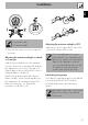
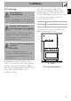
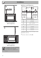
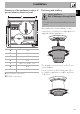
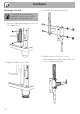
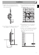
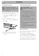

Installation
45
EN
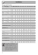
Burner and nozzle specifications tables
1 Natural gas G20 AUX SR R UR2 (int+ext)
Rated heating capacity (kW)
1.0 1.8 2.9 4.2
Nozzle diameter (1/100 mm)
72 97 120 75+135
Pre-chamber (printed on nozzle)
(X) (Z) (H9) (H1)+(H3)
Reduced flow rate (W)
400 500 800 1900
2 Natural gas G20 AUX SR R UR2 (int+ext)
Rated heating capacity (kW)
1.0 1.8 2.9 4.2
Nozzle diameter (1/100 mm)
72 94 113 75+127
Pre-chamber (printed on nozzle)
(X) (Z) (H8) (H1)+(H3)
Reduced flow rate (W)
400 500 800 1900
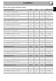
3 Natural gas G25 AUX SR R UR2 (int+ext)
Rated heating capacity (kW)
1.0 1.8 2.8 4.0
Nozzle diameter (1/100 mm)
72 94 120 75+135
Pre-chamber (printed on nozzle)
(X) (Y) (H9) (H1)+(H3)
Reduced flow rate (W)
400 500 800 1900
4 Natural gas G25.1 AUX SR R UR2 (int+ext)
Rated heating capacity (kW)
1.0 1.8 2.9 4.2
Nozzle diameter (1/100 mm)
77 100 134 75+138
Pre-chamber (printed on nozzle)
(F1) (Y) (F3) (H1)+(F3)
Reduced flow rate (W)
400 500 800 1900
5 Natural gas G25 AUX SR R UR2 (int+ext)
Rated heating capacity (kW) 1.0 1.8 2.9 4.1
Nozzle diameter (1/100 mm) 77 100 134 80+145
Pre-chamber (printed on nozzle) (F1) (Y) (F3) (Y)+(H3)
Reduced flow rate (W) 400 500 800 1900
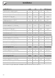
6 Natural gas G27 AUX SR R UR2 (int+ext)
Rated heating capacity (kW)
1.0 1.8 2.9 4.2
Nozzle diameter (1/100 mm)
77 105 138 80+148
Pre-chamber (printed on nozzle)
(F1) (Y) (F3) (H1)+(F3)
Reduced flow rate (W)
400 500 800 1900
7 Natural gas G2.350 AUX SR R UR2 (int+ext)
Rated heating capacity (kW)
1.0 1.8 2.9 4.0
Nozzle diameter (1/100 mm)
94 120 165 100+190
Pre-chamber (printed on nozzle)
(Y) (Y) (F3) (0)+(H3)
Reduced flow rate (W)
400 500 800 1900