Contents 1.1 1.2 1.3 1.4 1.5 1.6 1.7 General safety instructions Manufacturer liability Appliance purpose Identification plate This user manual Disposal How to read the user manual 2 Description 2.1 2.2 2.3 2.4 2.5 General Description Cooking hob Control panel Other parts Available accessories 3 Use 3.1 3.2 3.3 3.4 3.5 3.6 3.7 Instructions Cleaning the surfaces Cleaning the hob Cleaning the door Cleaning the oven cavity Extraordinary maintenance 5 Installation 5.1 5.2 5.3 5.4 5.
Instructions 1 Instructions 1.1 General safety instructions Risk of personal injury • During use the appliance and its accessible parts become very hot. Never touch the heating elements during use. • Protect your hands by wearing oven gloves when moving food inside the oven. • Never try to put out a fire or flames with water: turn off the appliance and smother the flames with a fire blanket or other appropriate cover.
• If you need to move food or at the end of cooking, open the door 5 cm for a few seconds, let the steam come out, then open it fully. • Do not open the storage compartment (where present) when the oven is on and still hot. • The items inside the storage compartment could be very hot after using the oven. • DO NOT USE OR STORE FLAMMABLE MATERIALS IN THE STORAGE COMPARTMENT (IF AVAILABLE) OR NEAR THE APPLIANCE. • DO NOT USE AEROSOLS IN THE VICINITY OF THIS APPLIANCE WHILST IT IS IN USE.
Instructions • DO NOT USE THE APPLIANCE TO HEAT ROOMS FOR ANY REASON. • Do not spray any spray products near the oven. • Do not use plastic cookware or containers for cooking. • Do not place sealed tins or containers in the oven cavity. • Remove all trays and racks which are not required during cooking. • Do not cover the bottom of the oven cavity with aluminium or tin foil sheets. • Do not place pans or trays directly on the bottom of the oven cavity.
Installation • THIS APPLIANCE MUST NOT BE INSTALLED IN A BOAT OR CARAVAN. • This appliance must not be installed on a pedestal. • Position the appliance into the cabinet cut-out with the help of a second person. • To prevent any possible overheating, the appliance should not be installed behind a decoration door or a panel. • Have the gas connection performed by authorised staff.
Instructions For this appliance • Ensure that the appliance is switched off before replacing the bulb. • Do not rest any weight or sit on the open door of the appliance. • Take care that no objects are stuck in the doors. 1.
To dispose of the appliance: • Cut the power supply cable and remove it along with the plug. Power voltage Danger of electrocution • Disconnect the mains power supply. • Unplug the appliance. • Deliver the appliance to the appropriate recycling centre for electrical and electronic equipment waste, or return it to the retailer when purchasing an equivalent product, on a one for one basis. Our appliances are packaged in non-polluting and recyclable materials.
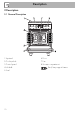
Description 2 Description 2.
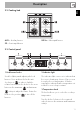
Description EN 2.2 Cooking hob AUX = Auxiliary burner SR = Semi-rapid burner UR-3c = Ultra-rapid burner 2.3 Control panel 1 Hob burner knobs 2 Indicator light Used for lighting and adjusting the hob burners. Press and turn the knobs anticlockwise to in order to light the relative burners. Turn the knobs to the zone between the maximum and minimum The indicator light comes on to indicate that the oven is heating up. It turns off as soon as it reaches the set temperature.
Description 4 Digital programmer Interior lighting Useful for displaying the current time, setting programmed cooking operations and programming the minute minder timer. The appliance’s interior lighting comes on: • when the door is opened; • when any function is selected, apart from 5 Function knob the The oven’s various functions are suitable for different cooking modes. After selecting the required function, set the cooking temperature using the temperature knob. function.
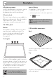
Description Ring reducer EN Deep tray Useful when using small cookware. WOK ring Useful for collecting fat from foods placed on the rack above and for cooking pies, pizzas and baked desserts. Tray rack Useful when using a wok. Not all accessories are available on some models. To be placed over the top of the tray; for cooking foods which may drip. The oven accessories intended to come into contact with food are made of materials that comply with the provisions of current legislation.
Use 3 Use 3.1 Instructions High temperature inside the oven during use Danger of burns • Keep the oven door closed during cooking. • Protect your hands wearing heat resistant gloves when moving food inside the oven. • Do not touch the heating elements inside the oven. • Do not pour water directly on very hot trays. • Keep children under the age of 8 away from the oven when it is in use.
High temperature inside the storage compartment Danger of fire or explosion • Do not spray any spray product near the appliance. • Do not use or leave flammable materials near the appliance or the storage compartment. • Do not use plastic cookware or containers for cooking. • Do not place sealed tins or containers in the oven cavity. • Do not leave the appliance unattended during cooking operations where fats and oils could be released. • Remove all trays and racks which are not required during cooking.
Use 3.2 Using the accessories Racks and trays Ring reducers Racks and trays have to be inserted into the side guides until they come to a complete stop. • The mechanical safety locks that prevent the rack from being taken out accidentally have to face downwards and towards the oven back. The ring reducers must be placed on the hob grids. Make sure they are placed properly. Tray rack The tray rack has to be inserted into the tray.
Use All the appliance’s control and monitoring devices are located together on the front panel. The burner controlled by each knob is shown next to the knob. The appliance is equipped with an electronic ignition device. Simply press the knob and turn it counterclockwise to the maximum flame symbol, until the burner ignites. If the burner does not light in the first 15 seconds, turn the knob to and wait 60 seconds before trying again.
Use 3.4 Using the oven Switching on the oven To switch the oven on: 1. Select the cooking function using the function knob. 2. Select the temperature using the temperature knob. Functions list Static As the heat comes from above and below at the same time, this system is particularly suitable for certain types of food. Traditional cooking, also known as static cooking, is suitable for cooking just one dish at a time.
Fan with round heating element The combination of the fan and the round heating element (incorporated in the rear of the oven) allows you to cook different foods on several levels, as long as they need the same temperatures and same type of cooking. Hot air circulation ensures instant and even distribution of heat. It will be possible, for instance, to cook fish, vegetables and biscuits simultaneously (on different levels) without odours and flavours mingling.
Use Timed cooking Setting the time If the time is not set, the oven will not switch on. On the first use, or after a power failure, the digits will be flashing on the appliance’s display. 1. Hold down the clock key for two seconds. The dot between the hours and the minutes flashes. 2. The time can be set via the value increase key and value decrease key . Keep the key pressed in to increase or decrease rapidly. 3. Wait 7 seconds. The dot between the hours and the minutes stops flashing. 4.
Use to reset the It is not possible to set a cooking time of more than 10 hours. To cancel the set programming press and hold down the value increase and the value decrease keys at the same time and then turn the oven off manually. 4. Use the or key to set the required minutes. (for example 1 hour) 5. Press the menu key 1. Set the cooking time as described in the previous point “Timed cooking”. 2. Hold the menu key 2 seconds. down for 3. Press the menu key again.
Use 10. Return the function and temperature knobs to 0. 11. To turn off the buzzer just press any key of the programmer clock. 12. Press the and keys at the same time to reset the set program. It is not possible to set a cooking time of more than 10 hours. It is not possible to set a programmed cooking time of more than 24 hours. After setting, hold the menu key down for 2 seconds to display the cooking time remaining. Press the menu key again.
3.6 Using the storage compartment Modifying the set data 1. Press the clock key . 2. Use the value increase and value decrease keys to set the number of minutes required. The storage compartment is at the bottom of the cooker. To open it, pull the handle towards you. It can be used to store cookware or metallic objects necessary when using the appliance. Deleting the set data 1. Press the clock key . 2. Hold down the value increase and value decrease keys at the same time. 3.
Use Advice for cooking with the Grill Advice for defrosting and proving • Meat can be grilled even when it is put into the cold oven or into the preheated oven if you wish to change the effect of the cooking. • When using the Fan with grill function, we recommend that you preheat the oven before grilling. • We recommend placing the food at the centre of the rack. • With the Grill function, we recommend that you turn the temperature knob to the maximum value to optimise cooking.
Use EN Cooking information table Weight (kg) Function Shelf Temperature (°C) Lasagne Pasta bake 3-4 3-4 Static Static 1 1 220 - 230 220 - 230 45 - 50 45 - 50 Roasted veal Pork loin Sausages Roast beef Roast rabbit Turkey breast Roast pork neck Roast chicken 2 2 1.5 1 1.5 3 2-3 1.
Cleaning and maintenance 4 Cleaning and maintenance 4.1 Instructions Improper use Risk of damage to surfaces • Do not use steam jets to clean the appliance. • Do not use cleaning products containing chlorine, ammonia or bleach on parts made of steel or that have metallic surface finishes (e.g. anodizing, nickelor chromium-plating). • Do not use abrasive or corrosive detergents (e.g. scouring powders, stain removers and metallic sponges) on glass parts.
4.3 Cleaning the hob Flame-spreader crowns and burner caps Knobs For easier cleaning, the flame-spreader crowns and the burner caps can be removed. Wash them in hot water and nonabrasive detergent. Carefully remove any encrustation, then wait until they are perfectly dry. Refit the flame-spreader crowns making sure that they are correctly positioned in their housings with their respective burner caps.
Cleaning and maintenance 4.4 Cleaning the door Removing the door For easier cleaning, the door can be removed and placed on a towel. To remove the door proceed as follows: 1. Open the door completely and insert two pins into the holes on the hinges indicated in the figure. 3. To reassemble the door, put the hinges in the relevant slots in the oven, making sure that grooved sections A are resting completely in the slots.
Removing the internal glass panes For easier cleaning, the internal glass panes of the door can be removed. 1. Remove the internal glass pane by pulling the rear part gently upwards following the movement indicated by the arrows (1). This way, the 4 pins attached to the glass detach from their housings in the door. 2. Then, pull the front part upwards (2). 3. Remove the intermediate glazing pane by lifting it upwards.
Cleaning and maintenance 4.5 Cleaning the oven cavity Cleaning of racks and trays For the best oven cavity upkeep, clean it regularly after having allowed it to cool. Avoid letting food residue dry inside the oven cavity, as this could damage the enamel. Take out all removable parts. Clean the racks and trays with warm water and non-abrasive detergents. Carefully rinse and dry damp parts.
Vapour Clean Vapor Clean is an assisted cleaning procedure which facilitates the removal of dirt. Thanks to this process, it is possible to clean the inside of the oven very easily. The dirt residues are softened by the heat and water vapour for easier removal afterwards. • Spray a water and washing up liquid solution inside the oven using a spray nozzle. Direct the spray against the side walls, upwards, downwards and towards the deflector.
Cleaning and maintenance End of the Vapor Clean cycle 4.6 Extraordinary maintenance 4. Open the door and wipe away the less stubborn dirt with a microfibre cloth. 5. Use a non-scratch sponge with brass filaments on hard to remove deposits. 6. In case of grease residues use specific oven cleaning products. 7. Remove the water left inside the oven.
Cleaning and maintenance 4. Slide out and remove the light bulb. EN Replacing the internal light bulb Live parts Danger of electrocution • Unplug the appliance from the mains. • Wear protective gloves. 1. Remove all accessories from inside the oven cavity. 2. Remove the rack/tray support frames. 3. Remove the bulb cover using a tool (e.g. a screwdriver). Take care not to scratch the enamel of the oven cavity wall. Do not touch the halogen light bulb directly with your fingers, use an insulating material.
Installation 5 Installation 5.1 Gas connection (not valid for the UK) For installation in the UK, please refer to the “Local specifications for UK gas appliances installation” booklet. Gas leak Danger of explosion General information Connection to the gas mains can be made using a continuous wall steel hose in compliance with the guidelines established by the standards in force. The appliance is preset for natural gas G20 (2H) at a pressure of 20 mbar.
Carefully screw the hose connector 3 to the appliance’s gas connector 1 (½” thread ISO 228-1), placing the seal 2 between them. The hose connector 4 can also be screwed to the hose connector 3, depending on the diameter of the gas hose used. After having tightened the hose connector(s), push the gas hose 6 onto the hose connector and secure it with the clamp 5 that is compliant with the standard in force.
Installation Connection to LPG Room ventilation Use a pressure regulator and make the connection on the gas cylinder following the guidelines set out in the standards in force. The appliance should be installed in rooms that have a permanent air supply in accordance with the standards in force. The room where the appliance is installed must have enough air flow for the regular combustion of gas and the necessary air change in the room itself.
5.2 Adaptation to different types of gas In case of operation with other types of gas, the burner nozzles must be changed and the minimum flame adjusted on the gas taps. Replacing nozzles 1. Remove the grids, burner caps and flame-spreader crowns in order to access the burner cups.
Installation Adjusting the minimum setting for LPG Tighten the screw located at the side of the cock rod clockwise all the way. Following adjustment to a gas other than the one originally set in the factory, replace the gas setting label on the appliance with the one corresponding to the new gas. The label is inserted inside the nozzle pack (where present). Lubricating the gas taps 3. Reposition the burners in their respective housings.
Gas types and Countries IT GB-IE FR-BE DE Gas types AT ES PT SE RU DK PL HU 1 Natural gas G20 G20 20 mbar • • • • • • • • • • • G20/25 20/25 mbar 2 Natural gas G20 G20 • 25 mbar 3 Natural gas G25.1 G25.1 • 25 mbar 4 Natural gas G25 G25 • 20 mbar 5 Natural gas G2.350 G2.
Installation Burner and nozzle characteristics tables 1 Natural gas G20 - 20 mbar Rated heating capacity (kW) Nozzle diameter (1/100 mm) Pre-chamber (printed on nozzle) Reduced flow rate (W) 2 Natural gas G20 - 25 mbar Rated heating capacity (kW) Nozzle diameter (1/100 mm) Pre-chamber (printed on nozzle) Reduced flow rate (W) 3 Natural gas G25.
6 LPG G30/31 - 30/37 mbar Rated heating capacity (kW) Nozzle diameter (1/100 mm) Pre-chamber (printed on nozzle) Reduced flow rate (W) Rated flow rate G30 (g/h) Rated flow rate G31 (g/h) 7 LPG G30/31 - 37 mbar Rated heating capacity (kW) Nozzle diameter (1/100 mm) Pre-chamber (printed on nozzle) Reduced flow rate (W) Rated flow rate G30 (g/h) Rated flow rate G31 (g/h) 8 LPG G30/31 - 50 mbar Rated heating capacity (kW) Nozzle diameter (1/100 mm) Pre-chamber (printed on nozzle) Reduced flow rate (W) Rated flo
Installation 5.3 Positioning Heavy appliance Crushing hazard • Position the appliance into the cabinet cut-out with the help of a second person. Pressure on the open door Risk of damage to the appliance • Never use the oven door to lever the appliance into place when fitting. • Avoid exerting too much pressure on the door when open. Any wall units positioned above the worktop of the appliance must be at a minimum distance of at least Y mm.
Installation B - Class 2 subclass 1 (Built-in appliance) A 600 mm B 600 mm C1 D min. 150 mm 900 - 915 mm H 750 mm I 450 mm L2 600 mm EN Appliance overall dimensions 1 Minimum distance from side walls or other flammable material. 2 Minimum cabinet width (=A). C - Class 2 subclass 1 (Built-in appliance) The appliance must be installed by a qualified technician and according to the regulations in force.
Installation Dimensions of the appliance: locations of gas and electric connections (mm) Positioning and levelling Heavy appliance Risk of damage to the appliance • Insert the front feet first and then the rear ones. After making the electrical and/or gas connections, screw the four adjustable feet supplied with the appliance. A 124 B 32 C 42 D 650 F min. 70 - max. 110 H 803 L 598 E = Electrical connection G = Gas connection 44 The appliance must sit level on the floor to ensure stability.
Installation 3. Assemble the fastening bracket. EN Fastening to the wall The anti-tip devices must be installed in order to prevent the appliance from tipping over. 1. Screw the wall fastening plate to the rear of the appliance. 2. Adjust the height of the 4 feet. 4. Align the base of the hook on the fastening bracket with the base of the slot on the wall fastening plate.
Installation 5. Align the base of the fastening bracket with the ground and tighten the screws to fix the measurements. 6. Use 50 mm for the distance from the side of the appliance to the bracket holes. 46 7. Move the bracket onto the wall and mark the position of the holes to be drilled in the wall. 8. After drilling the holes in the wall, use wall plugs and screws to fasten the bracket to the wall. 9.
Assembling the upstand The upstand provided is an integral part of the product; it must be fastened to the appliance prior to installation. The upstand must always be positioned and secured correctly on the appliance. 1. Loosen the 4 screws (A) on the back of the hob (2 for each side) using a screwdriver. 2. Place the upstand on the hob. 3. Align the slots of the upstand (B) with the screws (A). 4. Secure the upstand to the hob by tightening the 4 screws previously loosened. 5.
Installation 5.5 Electrical connection Power voltage Danger of electrocution • Have the electrical connection performed by authorised technicians. • Use personal protective equipment. • The appliance must be connected to ground in compliance with electrical system safety standards. • Disconnect the mains power supply. • Do not pull the cable to remove the plug. • Use cables withstanding a temperature of at least 90°C. • The tightening torque of the screws of the terminal board leads must be 1.5 - 2 Nm.