
Datasheet


Defi nition of Symbol
The abbreviations F.O.F. / P.T. / O.T. / T.T. shown in this
catalogue are detailed below.
F.O.F.
P.T.
O.T.
T.T.
P.T.
O.T.
T.T.
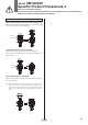
¡F.O.F. <Full Operating Force>
Required force to total travel position
¡P.T. <Pre-travel>
From free position to initial valve operating position
¡O.T. <Over Travel>
From initial valve operating position to total travel position
¡T.T. <Total Travel>
From free position to total travel position
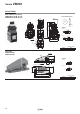
Design
Warning
1. This product cannot be used for applications in
which the pressure must be sealed.
Since the VM100 and VM200 are poppet type valves, fl uid fl ows
backward when the pressure on port 2 (A) rises.
Since the valves are subject to air leakage, they cannot be
used for applications such as holding pressure (including
vacuum).
2. Not suitable for use as an emergency shutoff valve
This mechanical valve is not designed for safety applications
such as an emergency shutoff valve. If the valves are used for
the mentioned applications, additional safety measures should
be adopted.
Mounting
Warning
1. When installing the mechanical operation type
mechanical valves, adjust the position so that the
valves do not operate over the operating limit range.
Operating over the limit could damage the mechanical valve or
actuator, and lead to equipment malfunction.
2. P.T. depends on pressure or differences between the
individual product specifi cations. In order to ensure
that the valve opens, keep the operating stroke
value for the mechanical operation type within the
range specifi ed by the following formula.
Operating stroke = (P.T. + 0.5 x O.T.) to (P.T. + O.T. – 0.1)
Operating Stroke Range
Series Actuator type
Operating stroke
[mm]
VM100
Basic 2.2 to 2.9
Roller lever 4.3 to 5.4
One way roller lever 4.3 to 5.4
Straight plunger 2.7 to 3.4
Roller plunger 2.7 to 3.4
Cross roller plunger 2.7 to 3.4
VM200
Basic 4 to 4.9
Roller lever 8.7 to 10.9
One way roller lever 9.5 to 11.9
Straight plunger 4.5 to 5.4
Roller plunger 4.5 to 5.4
Cross roller plunger 4.5 to 5.4
For straight and roller plunger types, there is a groove indicating
P.T. and T.T. for stroke adjustment.
T.T.
O.T.
P.T.
T.T.
O.T.
P.T.
3. Do not make any alterations to the valve body, such
as enlarging the body mounting holes.
As doing so could lead to unexpected abnormal conditions
such as air leakage.
Operation
Warning
1. Operate the manual operation type mechanical
valves (such as push button, twist selector and
toggle lever types) with your fi nger.
The use of equipment such as a cylinder, cam or hammer, can
result in the actuator and the valve being damaged.
Do not operate over the operation limit. If excessive operation
force is applied over total travel position, actuator part can get
deformed and lead to equipment malfunction.
Series VM100/200
Specific Product Precautions 1
Be sure to read before handling.
Refer to back cover for Safety Instructions and “Handling Precautions for SMC Products”
(M-E03-3) for 3/4/5 Port Solenoid Valve Precautions.
Mounting
Warning
23