
Datasheet

Standard Specifications
Valve construction
Fluid
Note 2)
Withstand pressure MPa
Ambient temperature °C
Fluid temperature °C
Environment
Valve leakage cm
3
/min
Mounting orientation
Vibration/Impact m/s
2
Note 4)
Rated voltage
Allowable voltage fluctuation
%
Coil insulation type
Enclosure
Note 5)
Power consumption W
Note 3)
Direct operated poppet
Water (except waste water or agricultural water), Air, Low vacuum
2.0
–10 to 50
1 to 50 (with no freezing)
Location without corrosive or explosive gases
0 (with water pressure)
Unrestricted
30/150
24VDC, 12VDC, 100VAC, 110VAC, 200VAC, 220VAC (50/60Hz)
±10% of rated voltage
Class B
Dust proof (equivalent to IP40)
2.5 (VDW10), 3 (VDW20/30)
Characteristic Specifications
VDW10
VDW20
VDW30
Model
ø1
ø1.6
ø1.6
ø2.3
ø3.2
ø2
ø3
ø4
0.9
0.4
0.7
0.4
0.2
0.8
0.4
0.2
0.54 (0.03)
1.2 (0.07)
1.2 (0.07)
3.2 (0.18)
5.8 (0.3)
2.8 (0.16)
5.0 (0.28)
8.0 (0.44)
0.4
0.2
0.2
0.1
0.05
0.2
0.1
0.05
Orifice
size
mm
Weight
kg
Port size
M5
M5
1/8 (6A)
1/8 (6A)
1/4 (8A)
Maximum operating
pressure
differential MPa
Note 1)
Pressure port 1 Pressure port 2
0.08
0 to 1.0
0.1
1/8: 0.23
1/4: 0.26
Valve specifications
Coil
Specifications
Operating
pressure
range
MPa
Note 2)
Effective area
mm²
(Cv factor)
Note 1) Consult SMC when used under conditions which may cause condensation on the exterior of the product.
Note 2) When used with pure water, select "L" (stainless steel, FKM) for the material type.
Note 3) Since AC coil specifications include a rectifying device, there is no difference in power consumption for starting and
holding.
In case of 110/220VAC, VDW10 is 3W and VDW20/30 is 3.5W.
Note 4) Vibration resistance … No malfunction when tested with one sweep of 5 to 200Hz in the axial direction and at a
right angle to the armature, in both energized and deenergized states.
Impact resistance … No malfunction when tested with a drop tester in the axial direction and at a right angle to
the armature, one time each in energized and deenergized states
Note 5) Consult SMC regarding drip-proof specifications (equivalent to IP54).
Note 1) The maximum operating pressure differential changes depending on the flow direction of the fluid. Refer to page
21 for details.
Note 2) For low vacuum specifications, the operating pressure range is 1Torr (1.33 x 10
² Pa) to 1.0MPa.
Consult SMC if used below 1Torr (1.33 x 10
² Pa).
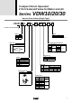
Series
VDW10/20/30
2