
Datasheet
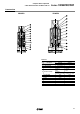


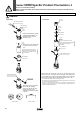

Replacement Parts Fluid Flow Direction
Solenoid coil part numbers
1
2
3
10
20, 200
30, 300
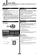
Series
VDW
Nil
L1
Note)
300mm
600mm
Lead wire length
1
2
3
4
5
6
100VAC
200VAC
110VAC
220VAC
24VDC
12VDC
Voltage
B
C1
C2
20, 200
10, 30
300
Type
Note 1)
Clip part numbers (2 port)
AZ-T-VDW
How to Order Valves
(Refer to pages 1, 5 and 11.)
01B1
Note) Type L1 is optional.
2
3
10, 20
30
Series
VDW 20 102
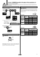
Piping to 3 Port Valve N.O. Port
Caution
Socket
Cover
When piping to an N.O. port, be sure to perform piping work
while holding the socket with a wrench or other tool. Refer to
page 18 for other precautions related to piping.
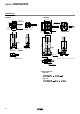
Caution
The maximum operating pressure differential differs depending
on the flow direction of the fluid. If the pressure differential at
each port exceeds the values in the table below, valve
leakage may occur.
Model
VDW10
VDW20
VDW30
ø1
ø1.6
ø1.6
ø2.3
ø3.2
ø2
ø3
ø4
Orifice size
mm
Maximum operating pressure
differential MPa
Pressure port 1
0.9
0.4
0.7
0.4
0.2
0.8
0.4
0.2
Pressure port 2
Note 1)
0.4
0.2
0.2
0.1
0.05
0.2
0.1
0.05
2 port valve
Note) When applying pressure from port 2, be careful to avoid vibration and impacts, etc.
OUT
(2)
(1)
IN
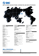
Model
VDW200
VDW300
ø1
ø1.6
ø2
ø3
ø4
Orifice size
mm
Maximum operating pressure
differential MPa
Pressure port 1
0.9
0.7
0.8
0.4
0.2
Pressure ports 2, 3
Note 1 & 2)
0.3
0.1
0.2
0.1
0.05
3 port valve
N.C.
(2)
N.O.
(3)
(1)
IN
2
Note 1) In case of a type C coil (for 10, 30, 300), the cover will be an integrated
type.
To have a label on the cover, enter the part number below together with
the coil part number.
Note 1) Indicates the maximum operating pressure differential for pressure ports 2 and 3.
Note 2) When the port 2 pressure is the higher pressure, be careful to avoid vibration and
impacts, etc.
21
Series VDW/Specific Product Precautions 2
Be sure to read before handling.
Refer to pages 16 through 19 for safety instructions and precautions for 2/3 port solenoid valve for
fluid control.