
Datasheet
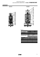


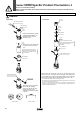

Replacement of the Solenoid Coil
Caution
Clip
Cover
Cover
Flat head screw driver
2 port valve 3 port valve
Tube assembly
Socket
O-ring
Plate
Wave washer
Cover
Coil assembly
Fixed armature threads
Coil assembly
Push the clip in direction (1) with
a flat head screw driver, etc.,
and remove it from the tube
assembly groove.
1
2
3
Remove the cover in direction (2),
and replace the coil assembly.
In case of types 10 and 30, the
cover alone cannot be removed
because it is integrated with the
coil assembly.
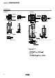
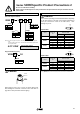
After replacing the coil, insert the
clip into the tube assembly
groove from direction (3). After
inserting it into the groove,
confirm the position and condition
of the clip.
Tube assembly groove
Center of clip
OK NG
Inserted position
Inserted condition
After removing the socket with a wrench, etc., lift off the plate, wave
washer and cover, and replace the coil assembly. After replacing the
coil, first tighten the socket by hand while holding down the plate and
wave washer, and then tighten it further with a torque of 0.8 to 1N⋅ m .
∗ Precautions when attaching and removing the socket
• Be careful that the O-ring installed on the bottom (plate side) of the socket does
not fall out or become chewed up, etc.
• Be sure to hold the body with a wrench, etc., and tighten the socket within the
tightening torque range given above. If excessive torque is applied, there is a
danger of damaging the threads.
Note
In case of type 300, the cover
alone cannot be removed because
it is integrated with the coil
assembly.
Note
Series VDW/Specific Product Precautions 1
Be sure to read before handling.
Refer to pages 16 through 19 for safety instructions and precautions for 2/3 port solenoid valve for
fluid control.
20