USER GUIDE 300Mbps Wireless-N Access Point/Repeater SMCWEBS-N
SMCWEBS-N User Guide 20 Mason Irvine, CA 92618 Phone: (949) 679-8000 January 2010 Pub.
Information furnished by SMC Networks, Inc. (SMC) is believed to be accurate and reliable. However, no responsibility is assumed by SMC for its use, nor for any infringements of patents or other rights of third parties which may result from its use. No license is granted by implication or otherwise under any patent or patent rights of SMC. SMC reserves the right to change specifications at any time without notice. Copyright © 2010 by SMC Networks, Inc.
WARRANTY AND PRODUCT REGISTRATION To register SMC products and to review the detailed warranty statement, please refer to the Support Section of the SMC Website at http:// www.smc.com.
COMPLIANCES FEDERAL COMMUNICATION COMMISSION INTERFERENCE STATEMENT This equipment has been tested and found to comply with the limits for a Class B digital device, pursuant to Part 15 of the FCC Rules. These limits are designed to provide reasonable protection against harmful interference in a residential installation.
COMPLIANCES IC STATEMENT This Class B digital apparatus complies with Canadian ICES-003. Operation is subject to the following two conditions: (1) this device may not cause interference, and (2) this device must accept any interference, including interference that may cause undesired operation of the device. Cet appareil numérique de la classe B conforme á la norme NMB-003 du Canada.
COMPLIANCES This device is intended for use in the following European Community and EFTA countries: ◆ Austria ◆ Denmark ◆ Greece ◆ Latvia ◆ Norway ◆ Slovenia ◆ Belgium ◆ Estonia ◆ Hungary ◆ Lithuania ◆ Poland ◆ Spain ◆ Bulgaria ◆ Finland ◆ Iceland ◆ Luxembourg ◆ Portugal ◆ Sweden ◆ Cyprus ◆ France ◆ Ireland ◆ Malta ◆ Romania ◆ Switzerland ◆ Czech Republic ◆ Germany ◆ Italy ◆ Netherlands ◆ Slovakia ◆ United Kingdom NOTE: The user must use the configuration utility provided with this product to ensure t
COMPLIANCES German Deutsch Hiermit erklärt Manufacturer, dass sich dieser/diese/dieses Radio LAN device in Übereinstimmung mit den grundlegenden Anforderungen und den anderen relevanten Vorschriften der Richtlinie 1999/5/EG befindet". (BMWi) Hiermit erklärt Manufacturer die Übereinstimmung des Gerätes Radio LAN device mit den grundlegenden Anforderungen und den anderen relevanten Festlegungen der Richtlinie 1999/5/EG.
ABOUT THIS GUIDE PURPOSE This guide gives specific information on how to install the Wireless-N Access Point/Repeater and its physical and performance related characteristics. It also gives information on how to operate and use the management functions of the Wireless-N Access Point/Repeater. AUDIENCE This guide is for users with a basic working knowledge of computers. You should be familiar with Windows operating system concepts.
CONTENTS SECTION I WARRANTY AND PRODUCT REGISTRATION 4 COMPLIANCES 5 ABOUT THIS GUIDE 9 CONTENTS 10 FIGURES 13 TABLES 15 GETTING STARTED 1 INTRODUCTION 16 17 Key Hardware Features 17 Description of Capabilities 17 Package Contents 18 Hardware Description 18 LED Indicators 19 Ethernet LAN Ports 20 Power Connector 20 Reset Button 20 WPS Button 20 2 NETWORK PLANNING 21 LAN Access Point 21 Wireless Bridge 22 3 INSTALLING THE ACCESS POINT/REPEATER 23 System Requirements
CONTENTS Mounting on a Horizontal Surface 4 INITIAL CONFIGURATION SECTION II 25 26 Connecting to the Login Page 26 Home Page and Main Menu 27 Common Web Page Buttons 28 Setup Wizard 28 Step 1 - Language Selection 28 Step 2 - Time Settings 29 Step 3 - Wireless Security 29 Completion 30 WEB CONFIGURATION 5 NETWORK SETTINGS 31 32 LAN Setting 32 6 WIRELESS CONFIGURATION Basic Settings 34 34 HT Physical Mode Settings Advanced Settings 37 38 Advanced Wireless 38 Wi-Fi Multimedia 4
CONTENTS SECTION III System Status 61 Statistics 62 System Log 63 APPENDICES 65 A TROUBLESHOOTING 66 Diagnosing LED Indicators 66 Before Contacting Technical Support 66 B HARDWARE SPECIFICATIONS 68 C CABLES AND PINOUTS 70 Twisted-Pair Cable Assignments 70 10/100BASE-TX Pin Assignments 71 Straight-Through Wiring 71 Crossover Wiring 72 D LICENSE INFORMATION 73 The GNU General Public License 73 GLOSSARY 77 INDEX 81 – 12 –
FIGURES Figure 1: Top Panel 18 Figure 2: Rear Panel 19 Figure 3: LEDs 19 Figure 4: Operating as an Access Point 21 Figure 5: Operating as a Wireless Bridge 22 Figure 6: Operating as a Wireless Repeater 22 Figure 7: Wall Mounting 24 Figure 8: Login Page 27 Figure 9: Home Page 27 Figure 10: Wizard Step 1 - Language Selection 28 Figure 11: Wizard Step 2 - Time and SNTP Settings 29 Figure 12: Wizard Step 3 - Wireless Security and Encryption Settings 29 Figure 13: LAN Configuration 32
FIGURES Figure 32: System Management 57 Figure 33: Time Zone Settings 58 Figure 34: Firmware Upgrade 59 Figure 35: Configuration Settings 60 Figure 36: System Status 61 Figure 37: Statistics 62 Figure 38: System Log 63 Figure 39: RJ-45 Connector 70 Figure 40: Straight-through Wiring 72 Figure 41: Crossover Wiring 72 – 14 –
TABLES Table 1: Key Hardware Features 17 Table 2: LED Behavior 19 Table 3: WMM Access Categories 41 Table 4: LED Indicators 66 Table 5: 10/100BASE-TX MDI and MDI-X Port Pinouts 71 – 15 –
SECTION I GETTING STARTED This section provides an overview of the Wireless-N Access Point/Repeater, and describes how to install and mount the unit. It also describes the basic settings required to access the management interface and run the setup Wizard.
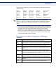
1 INTRODUCTION The Wireless-N Access Point/Repeater (SMCWEBS-N) supports an access point service that extends a local wired network to wireless clients. It is simple to configure and can be up and running in minutes. KEY HARDWARE FEATURES The following table describes the main hardware features of the Access Point/Repeater. Table 1: Key Hardware Features Feature Description 4 LAN Ports Four 100BASE-TX RJ-45 ports for local network connections.
CHAPTER 1 | Introduction Package Contents PACKAGE CONTENTS The Wireless-N Access Point/Repeater package includes: ◆ Wireless-N Access Point/Repeater (SMCWEBS-N) ◆ RJ-45 Category 5 network cable ◆ AC power adapter ◆ SMC Warranty Information Card ◆ Quick Installation Guide Inform your dealer if there are any incorrect, missing or damaged parts. If possible, retain the carton, including the original packing materials. Use them again to repack the product in case there is a need to return it.
CHAPTER 1 | Introduction Hardware Description Figure 2: Rear Panel Antennas Reset Button WPS Button Ethernet LAN RJ-45 Ports Power Socket LED INDICATORS The Wireless-N Access Point/Repeater includes seven status LED indicators, as described in the following figure and table. Figure 3: LEDs Power 802.11n Link/Activity LAN Link/Activity WPS Authentication Table 2: LED Behavior LED Status Description Power On Blue The unit is receiving power and is operating normally.
CHAPTER 1 | Introduction Hardware Description Table 2: LED Behavior (Continued) LED Status Description WLAN On/Blinking Blue The 802.11n radio is enabled and transmitting or receiving data through wireless links. Off The 802.11n radio is disabled. Blinking WPS authentication is in progress. Off WPS authentication is not in progress. On Blue The Ethernet LAN port is connected to a PC or server. Blinking The Ethernet port is connected and is transmitting/receiving data.
2 NETWORK PLANNING The Wireless-N Access Point/Repeater is designed as an access point that extends an existing wired network to support wireless users. It also supports use as a wireless repeater/bridge that can extend the range of the network or connect to remote LANs. This chapter explains some of the basic features of the Wireless-N Access Point/Repeater and shows some network topology examples in which the device is implemented.
CHAPTER 2 | Network Planning Wireless Bridge WIRELESS BRIDGE The IEEE 802.11 standard defines a Wireless Distribution System (WDS) for bridge connections between access points. The Wireless-N Access Point/Repeater can use WDS to forward traffic on links between units. Up to four WDS links can be specified for the Wireless-N Access Point/ Repeater. The WDS feature enables two basic functions to be configured in the wireless network.
3 INSTALLING THE ACCESS POINT/ REPEATER This chapter describes how to install the access point. SYSTEM REQUIREMENTS You must meet the following minimum requirements: ◆ An Internet access device (DSL or Cable modem) with an Ethernet port connection. ◆ An up-to-date web browser: Internet Explorer 6.0 or above or Mozilla Firefox 2.0 or above. LOCATION SELECTION Choose a proper place for the access point/repeater.
CHAPTER 3 | Installing the Access Point/Repeater Mounting the Device MOUNTING THE DEVICE The Wireless-N Access Point/Repeater can be mounted on any horizontal surface, or on a wall. The following sections describe the mounting options. MOUNTING ON A WALL The Wireless-N Access Point/Repeater should be mounted only to a wall or wood surface that is at least 1/2-inch plywood or its equivalent. To mount the unit on a wall, always use its wall-mounting slots.
CHAPTER 3 | Installing the Access Point/Repeater Mounting the Device MOUNTING ON A To keep the Wireless-N Access Point/Repeater from sliding on the surface, HORIZONTAL SURFACE the Wireless-N Access Point/Repeater has four rubber feet on the bottom of the unit. It is recommended to select an uncluttered area on a sturdy surface, such as a desktop or table. The unit can also be protected by securing all attached cables to a table leg or other nearby fixed structure.
4 INITIAL CONFIGURATION The Wireless-N Access Point/RepeaterWireless-N Access Point/Repeater offers a user-friendly web-based management interface for the configuration of all the unit’s features. Any PC directly attached to the unit can access the management interface using a web browser, such as Internet Explorer (version 6.0 or above).
CHAPTER 4 | Initial Configuration Home Page and Main Menu Figure 8: Login Page HOME PAGE AND MAIN MENU After logging in to the web interface, the Home page displays. The Home page shows the main menu and the method to access the Setup Wizard.
CHAPTER 4 | Initial Configuration Common Web Page Buttons COMMON WEB PAGE BUTTONS The list below describes the common buttons found on most web management pages: ◆ Apply – Applies the new parameters and saves them to memory. Also displays a screen to inform you when it has taken affect. Clicking ‘Apply’ returns to the home page. ◆ Cancel – Cancels the newly entered settings and restores the previous settings. ◆ Next – Proceeds to the next step. ◆ Previous – Returns to the previous screen.
CHAPTER 4 | Initial Configuration Setup Wizard STEP 2 - TIME The Step 2 page of the Wizard configures time zone and SNTP settings. SETTINGS Select a time zone according to where the device is operated. Click Next after completing the setup. Figure 11: Wizard Step 2 - Time and SNTP Settings The following items are displayed on this page: ◆ Current Time — Receives a time and date stamp from an SNTP server. ◆ Time Zone — Select the time zone that is applicable to your region.
CHAPTER 4 | Initial Configuration Setup Wizard The following items are displayed on this page: ◆ SSID Choice — The name of the wireless network service provided by the Wireless-N Access Point/Repeater. Clients that want to connect to the network must set their SSID to the same as that of the Wireless-N Access Point/Repeater. (Default: “SMC”) ◆ Security Mode — Specifies the security mode for the SSID. Select the security method and then configure the required parameters.
SECTION II WEB CONFIGURATION This section provides details on configuring the Wireless-N Access Point/ Repeater using the web browser interface.
5 NETWORK SETTINGS The Network Settings pages allow you to manage basic system configuration settings. LAN SETTING The Wireless-N Access Point/Repeater must have a valid IP address for management using a web browser and to support other features. The unit has a default IP address of 192.168.2.10. You can use this IP address or assign another address that is compatible with your existing local network. Click on “Network Settings” followed by “LAN.
CHAPTER 5 | Network Settings LAN Setting ◆ MAC Address — The shared physical layer address for the Wireless-N Access Point/Repeater’s LAN ports. ◆ Hostname — The hostname of the STATIC or DHCP client. ◆ IP Address — Valid IP addresses consist of four decimal numbers, 0 to 255, separated by periods. The default setting is 192.168.2.10. ◆ Subnet Mask — Indicate the local subnet mask. (Default: 255.255.255.0.
6 WIRELESS CONFIGURATION The wireless settings section displays configuration settings for the access point functionality of the Wireless-N Access Point/Repeater. It includes the following sections: ◆ “Basic Settings” on page 34 ◆ “Advanced Settings” on page 38 ◆ “WLAN Security” on page 43 ◆ “Wireless Distribution System (WDS)” on page 51 ◆ “Wi-Fi Protected Setup (WPS)” on page 54 ◆ “Station List” on page 56 BASIC SETTINGS The IEEE 802.
CHAPTER 6 | Wireless Configuration Basic Settings The Basic Settings page allows you to configure the wireless network name (Service Set Identifier or SSID) and set the wireless security method. Click on “Wireless Settings,” followed by “Basic.” Figure 14: Basic Settings The following items are displayed on this page: ◆ Wireless On/Off — Enables or Disable the radio. (Default: Enable) ◆ Network Mode — Defines the radio operating mode. (Default: 11g/n Mixed) ■ 11b/g mixed mode: Both 802.11b and 802.
CHAPTER 6 | Wireless Configuration Basic Settings ■ 11b/g/n mixed mode: All 802.11b/g/n clients can communicate with the Wireless-N Access Point/Repeater (up to 150 Mbps), but data transmission rates may be slowed to compensate for 802.11b/ g clients. ■ 11n only: Only 802.11n clients will be able to communicate with the Wireless-N Access Point/Repeater (up to 150 Mbps). ■ 11g/n mixed mode: Both 802.11g and 802.
CHAPTER 6 | Wireless Configuration Basic Settings HT PHYSICAL MODE The HT Physical Mode section on the Wireless Settings Advanced page SETTINGS includes additional parameters for 802.11n operation. Figure 15: HT Physical Mode Settings The following items are displayed in this section on this page: ◆ Channel Bandwidth — The Wireless-N Access Point/Repeater provides a channel bandwidth of 40 MHz by default giving an 802.11g connection speed of 108 Mbps (sometimes referred to as Turbo Mode) and a 802.
CHAPTER 6 | Wireless Configuration Advanced Settings ◆ Decline BA Request — Select to reject peer BA-Request or not. (Default: Disabled) ADVANCED SETTINGS The Advanced Settings page includes additional parameters concerning the wireless network and Wi-Fi Multimedia settings. NOTE: There are several variables to consider when selecting a radio mode that make it fully functional. Simply selecting the mode you want is not enough to ensure full compatibility for that mode.
CHAPTER 6 | Wireless Configuration Advanced Settings The following items are displayed in this section on this page: ◆ BG Protection Mode — Enables a backward compatible protection mechanism for 802.11b clients. There are three modes: (Default: Auto) ■ Auto — The unit enables its protection mechanism for 802.11b clients when they are detected in the network. When 802.11b clients are not detected, the protection mechanism is disabled. ■ On — Forces the unit to always use protection for 802.
CHAPTER 6 | Wireless Configuration Advanced Settings After receiving an RTS frame, the station sends a CTS (clear to send) frame to notify the sending station that it can start sending data. If the RTS threshold is set to 0, the access point always sends RTS signals. If set to 2347, the access point never sends RTS signals. If set to any other value, and the packet size equals or exceeds the RTS threshold, the RTS/CTS (Request to Send / Clear to Send) mechanism will be enabled.
CHAPTER 6 | Wireless Configuration Advanced Settings WMM defines four access categories (ACs): voice, video, best effort, and background. These categories correspond to traffic priority levels and are mapped to IEEE 802.1D priority tags (see Table 3). The direct mapping of the four ACs to 802.1D priorities is specifically intended to facilitate interoperability with other wired network QoS policies.
CHAPTER 6 | Wireless Configuration Advanced Settings ◆ WMM Parameters — Click the WMM Configuration button to set detailed WMM parameters. Figure 18: WMM Configuration The following items are displayed in the WMM Configuration window: ◆ AIFSN (Arbitration Inter-Frame Space) — The minimum amount of wait time before the next data transmission attempt. Specify the AIFS value in the range 0-15 microseconds.
CHAPTER 6 | Wireless Configuration WLAN Security ◆ ACM — The admission control mode for the access category. When enabled, clients are blocked from using the access category. (Default: Disabled) ◆ AckPolicy — By default, all wireless data transmissions require the sender to wait for an acknowledgement from the receiver. WMM allows the acknowledgement wait time to be turned off for each Access Category (AC) 0-3.
CHAPTER 6 | Wireless Configuration WLAN Security The Wireless-N Access Point/Repeater supports supports ten different security mechanisms that provide various levels of authentication and encryption depending on the requirements of the network. The Wireless-N Access Point/Repeater supports four SSID interfaces. Each SSID interface functions as a separate access point, and can be configured with its own security settings. Click on “Wireless Settings,” followed by “Basic”.
CHAPTER 6 | Wireless Configuration WLAN Security When you select to use WEP, be sure to define at least one static WEP key for user authentication or data encryption. Also, be sure that the WEP shared keys are the same for each client in the wireless network. Figure 21: Security Mode - WEP The following items are displayed in this section on this page: Security Mode — Configures the WEP security mode used by clients.
CHAPTER 6 | Wireless Configuration WLAN Security WPA PRE-SHARED Wi-Fi Protected Access (WPA) was introduced as an interim solution for the KEY vulnerability of WEP pending the adoption of a more robust wireless security standard. WPA2 includes the complete wireless security standard, but also offers backward compatibility with WPA. Both WPA and WPA2 provide an “enterprise” and “personal” mode of operation.
CHAPTER 6 | Wireless Configuration WLAN Security ■ AES — Uses Advanced Encryption Standard (AES) keys for encryption. WPA2 uses AES Counter-Mode encryption with Cipher Block Chaining Message Authentication Code (CBC-MAC) for message integrity. The AES Counter-Mode/CBCMAC Protocol (AESCCMP) provides extremely robust data confidentiality using a 128bit key. Use of AES-CCMP encryption is specified as a standard requirement for WPA2.
CHAPTER 6 | Wireless Configuration WLAN Security Figure 23: Security Mode - WPA The following items are displayed in this section on this page: Security Mode — Configures the WPA and WPA2 security modes used by clients. When using WPA or WPA2, be sure there is a RADIUS server in the connected wired network, and that the RADIUS settings are configured. See “IEEE 802.1X and RADIUS” on page 49 for more information. (Default: Disable) ◆ WPA — Clients using WPA with an 802.
CHAPTER 6 | Wireless Configuration WLAN Security CCMP) provides extremely robust data confidentiality using a 128bit key. Use of AES-CCMP encryption is specified as a standard requirement for WPA2. Before implementing WPA2 in the network, be sure client devices are upgraded to WPA2-compliant hardware. ■ TKIP/AES — Uses either TKIP or AES keys for encryption. WPA and WPA2 mixed modes allow both WPA and WPA2 clients to associate to a common SSID.
CHAPTER 6 | Wireless Configuration WLAN Security Figure 24: Security Mode - 802.1X The following items are displayed in this section on this page: Security Mode — Configures the 802.1X security mode used by clients. When using 802.1X, either with WPA/WPA2 or on its own, be sure there is a configured RADIUS server in the connected wired network. (Default: Disable) 802.1X WEP: Selects WEP keys for data encryption.
CHAPTER 6 | Wireless Configuration Wireless Distribution System (WDS) ACCESS POLICY The Wireless-N Access Point/Repeater provides a MAC address filtering facility. The access policy can be set to allow or reject specific station MAC addresses. This feature can be used to connect known wireless devices that may not be able to support the configured security mode.
CHAPTER 6 | Wireless Configuration Wireless Distribution System (WDS) Figure 26: Manual WDS MAC Address Configuration Wired Network WDS Link WD SL ink WD SL MAC: 00-22-2D-62-EA-11 WDS MAC List: 00-22-2D-62-EA-22 00-22-2D-62-EA-33 00-22-2D-62-EA-44 MAC: 00-22-2D-62-EA-44 WDS MAC List: 00-22-2D-62-EA-11 ink MAC: 00-22-2D-62-EA-22 WDS MAC List: 00-22-2D-62-EA-11 MAC: 00-22-2D-62-EA-33 WDS MAC List: 00-22-2D-62-EA-11 Figure 27: WDS Configuration Example Wired Network WDS Link WD SL ink WD
CHAPTER 6 | Wireless Configuration Wireless Distribution System (WDS) Figure 28: WDS Configuration The WDS settings configure WDS related parameters. Up to four MAC addresses can be specified for each unit in the WDS network. WDS links may either be manually configured (Bridge and Repeater modes) or autodiscovered (Lazy mode). The following items are displayed on this page: ◆ WDS Mode — Selects the WDS mode of the SSID. (Options: Disable, Lazy, Bridge, Repeater.
CHAPTER 6 | Wireless Configuration Wi-Fi Protected Setup (WPS) ■ Repeater: Operates as a wireless repeater, extending the range for remote wireless clients and connecting them to an AP connected to the wired network. The MAC addresses of WDS peers must be configured on the Wireless-N Access Point/Repeater. ◆ Physical — The radio media coding used on all WDS links. CCK corresponds to 11b, OFDM corresponds to 11g, and HTMIX corresponds to 11n.
CHAPTER 6 | Wireless Configuration Wi-Fi Protected Setup (WPS) The following items are displayed on this page: ◆ WPS — Enables WPS, locks security settings, and refreshes WPS configuration information. (Default: Disabled) Figure 30: WPS Configuration The following items are displayed on this page: WPS Summary — Provides detailed WPS statistical information. ◆ WPS Current Status — Displays if there is currently any WPS traffic connecting to the Wireless-N Access Point/Repeater.
CHAPTER 6 | Wireless Configuration Station List ◆ AP PIN — Displays the PIN Code for the Wireless-N Access Point/ Repeater. The default is exclusive for each unit. ◆ Reset WPS to Default — Resets the WPS settings to factory default values. WPS Config — Configures WPS settings for the Wireless-N Access Point/ Repeater.
7 ADMINISTRATION SETTINGS The Wireless-N Access Point/Repeater’s Administration Settings allow you to configure a management access password, set the system time, upgrade the system software, display the system status and statistics.
CHAPTER 7 | Administration Settings System Management The following items are displayed in the first two sections on this page: ◆ Language Settings — You can change the language displayed in web interface. Select the language of your choice from the drop-down list, then click “Apply”. (Options: English, Traditional Chinese, Simple Chinese, or Korean.
CHAPTER 7 | Administration Settings Firmware Upgrade FIRMWARE UPGRADE You can update the Wireless-N Access Point/Repeater firmware by using the Firmware Update facility. Figure 34: Firmware Upgrade The following items are displayed on this page: ◆ Firmware Upgrade — Allows you to upload new firmware manually by specifying a file path. Make sure the firmware you want to use is on the local computer by clicking Browse to search for the firmware to be used for the update.
CHAPTER 7 | Administration Settings Configuration Settings CONFIGURATION SETTINGS The Configuration Setting page allows you to save the Wireless-N Access Point/Repeater’s current configuration or restore a previously saved configuration back to the device. Figure 35: Configuration Settings The following items are displayed on this page: ◆ Export Settings — Saves the current configuration to a file locally.
CHAPTER 7 | Administration Settings System Status SYSTEM STATUS The System Information page displays basic system information and the displayed settings are for status information only and are not configurable on this page. This information is split into the three sections that follow. Figure 36: System Status The following items are displayed on this page: ◆ ◆ System Info — Displays the basic system information.
CHAPTER 7 | Administration Settings Statistics STATISTICS The Wireless-N Access Point/Repeater Traffic Statistics - Interfaces window displays received and transmitted packet statistics for all interfaces on the Wireless-N Access Point/Repeater. Figure 37: Statistics The following items are displayed on this page: ◆ Memory total — The total memory of this Wireless-N Access Point/ Repeater. ◆ Memory left — The available memory of this Wireless-N Access Point/ Repeater.
CHAPTER 7 | Administration Settings System Log ◆ Tx bytes — Displays the total number of bytes transmitted by the specified interface. SYSTEM LOG The Wireless-N Access Point/Repeater supports a logging process that controls error messages saved to memory or sent to a Syslog server. The logged messages serve as a valuable tool for isolating Wireless-N Access Point/Repeater and network problems. The System Log page displays the latest messages logged in chronological order, from the newest to the oldest.
CHAPTER 7 | Administration Settings System Log ◆ Clear — Removes the current system log messages from the System Log Table.
SECTION III APPENDICES This section provides additional information and includes these items: ◆ “Troubleshooting” on page 66 ◆ “Hardware Specifications” on page 68 ◆ “Cables and Pinouts” on page 70 ◆ “Glossary” on page 77 ◆ “Index” on page 81 – 65 –
A TROUBLESHOOTING DIAGNOSING LED INDICATORS Table 4: LED Indicators Symptom Action Power/LAN LEDs are off ◆ The AC power adapter may be disconnected. Check connections between the Access Point/Repeater, the power adapter, and the wall outlet. WLAN LED is off ◆ The access point radio has been disabled through it’s web management interface. Access the management interface using a web browser to enable the radio.
APPENDIX A | Troubleshooting Before Contacting Technical Support Then use the default user name “admin” and password “smcadmin” to access the management interface. 3. If all other recovery measure fail, and the Access Point/Repeater is still not functioning properly, take any of these steps: ■ Reset the Access Point/Repeater’s hardware using the web interface, or through a power reset.
B HARDWARE SPECIFICATIONS PORT INTERFACES LAN 1~4: 1 10/100BASE-TX port, RJ-45 connector, auto MDI/X (100-ohm, UTP cable; Category 5 or better) AC POWER ADAPTER Input: 100~240 VAC, 50/60 Hz Output: 5 V/ 1 A LED INDICATORS Power, WLAN (Wireless Local Area Network), WPS (Wi-Fi Protected Setup), LAN 1~4 (Local Area Network). NETWORK MANAGEMENT Web-browser TEMPERATURE Operating: 0 to 40 °C (32 to 104 °F) Storage: -20 to 70 °C (32 to 158 °F) HUMIDITY 20% to 85% (non-condensing) PHYSICAL SIZE 136 X 90.
APPENDIX B | Hardware Specifications SAFETY EN 60950-1 (2006) ENVIRONMENTAL ETSI EN 300 019-2-1 Class 1.2 (Storage) ETSI EN 300 019-2-2 Class 2.3 (Packaged) ETSI EN 300 019-2-3 Class 3.
C CABLES AND PINOUTS TWISTED-PAIR CABLE ASSIGNMENTS For 10/100BASE-TX connections, a twisted-pair cable must have two pairs of wires. For 1000BASE-T connections the twisted-pair cable must have four pairs of wires. Each wire pair is identified by two different colors. For example, one wire might be green and the other, green with white stripes. Also, an RJ-45 connector must be attached to both ends of the cable. NOTE: Each wire pair must be attached to the RJ-45 connectors in a specific orientation.
APPENDIX C | Cables and Pinouts 10/100BASE-TX Pin Assignments 10/100BASE-TX PIN ASSIGNMENTS Use unshielded twisted-pair (UTP) or shielded twisted-pair (STP) cable for RJ-45 connections: 100-ohm Category 3 or better cable for 10 Mbps connections. Also be sure that the length of any twisted-pair connection does not exceed 100 meters (328 feet).
APPENDIX C | Cables and Pinouts Crossover Wiring Figure 40: Straight-through Wiring EIA/TIA 568B RJ-45 Wiring Standard 10/100BASE-TX Straight-through Cable White/Orange Stripe Orange End A White/Green Stripe 1 2 3 4 5 6 7 8 Blue White/Blue Stripe Green White/Brown Stripe 1 2 3 4 5 6 7 8 End B Brown CROSSOVER WIRING If the twisted-pair cable is to join two ports and either both ports are labeled with an “X” (MDI-X) or neither port is labeled with an “X” (MDI), a crossover must be implemented in the
D LICENSE INFORMATION This product includes copyrighted third-party software subject to the terms of the GNU General Public License (GPL), GNU Lesser General Public License (LGPL), or other related free software licenses. The GPL code used in this product is distributed WITHOUT ANY WARRANTY and is subject to the copyrights of one or more authors. For details, refer to the section "The GNU General Public License" below, or refer to the applicable license as included in the source-code archive.
APPENDIX D | License Information The GNU General Public License GNU GENERAL PUBLIC LICENSE TERMS AND CONDITIONS FOR COPYING, DISTRIBUTION AND MODIFICATION 1. This License applies to any program or other work which contains a notice placed by the copyright holder saying it may be distributed under the terms of this General Public License.
APPENDIX D | License Information The GNU General Public License b). Accompany it with a written offer, valid for at least three years, to give any third party, for a charge no more than your cost of physically performing source distribution, a complete machine-readable copy of the corresponding source code, to be distributed under the terms of Sections 1 and 2 above on a medium customarily used for software interchange; or, c).
APPENDIX D | License Information The GNU General Public License 9. If the distribution and/or use of the Program is restricted in certain countries either by patents or by copyrighted interfaces, the original copyright holder who places the Program under this License may add an explicit geographical distribution limitation excluding those countries, so that distribution is permitted only in or among countries not thus excluded.
GLOSSARY 10BASE-T IEEE 802.3-2005 specification for 10 Mbps Ethernet over two pairs of Category 3 or better UTP cable. 100BASE-TX IEEE 802.3-2005 specification for 100 Mbps Fast Ethernet over two pairs of Category 5 or better UTP cable. 1000BASE-T IEEE 802.3ab specification for 1000 Mbps Gigabit Ethernet over four pairs of Category 5 or better UTP cable. ACCESS POINT An internetworking device that seamlessly connects wired and wireless networks.
GLOSSARY the Bootstrap Protocol (BOOTP), adding the capability of automatic allocation of reusable network addresses and additional configuration options. ENCRYPTION Data passing between the access point and clients can use encryption to protect from interception and evesdropping. ETHERNET A popular local area data communications network, which accepts transmission from computers and terminals. FTP File Transfer Protocol: A TCP/IP protocol used for file transfer.
GLOSSARY ODFM Orthogonal Frequency Division Multiplexing: OFDM allows multiple users to transmit in an allocated band by dividing the bandwidth into many narrow bandwidth carriers. SSID Service Set Identifier: An identifier that is attached to packets sent over the wireless LAN and functions as a password for joining a particular radio cell; i.e., Basic Service Set (BSS).
GLOSSARY WPA-PSK WPA Pre-shared Key: WPA-PSK can be used for small office networks with a limited number of users that may not need a high level of security. WPAPSK provides a simple security implementation that uses just a pre-shared password for network access.
INDEX NUMERICS 10/100BASE-TX pin assignments 71 802.
INDEX mounting on a wall 24 multicast-to-unicast convertion 43 multiple SSID 36 N network name, wireless 34, 36 network statistics 62 O standards, radio 68 station list, wireless 56 Statistics 62 statistics, system 62 status of system 61 straight-through cables 71 system defaults 60 system log 63 system requirements 23 System Status 61 system time 58 open system 43 T P Package Contents 18 password default 26 setting 58 PBC mode, WPS 56 physical size 68 PIN code, WPS 56 pinouts, cable 70 PMK cache per
SMCWEBS-N