
Brochure
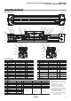


s3INKINPUTSPECIFICATIONS
WIRE.0.
s3OURCEINPUTSPECIFICATIONS
WIRE0.0
WIRE WIRE
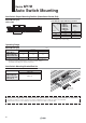
Main
circuit
of switch
Brown
Black
Blue
Load
(Power supply for switch and load are separate.)
Brown
Black
Blue
Main
circuit
of switch
Load
Main
circuit
of switch
Brown
Black
Blue
Load
Main
circuit
of switch
Brown
Blue
Load
Brown
Blue
Main
circuit
of switch
Load
Auto switch
Input
COM
Auto switch
Input
COM
Auto switch
Input
PLC internal circuit
COM
PLC internal circuit
PLC internal circuit
PLC internal circuit
Auto switch
Input
COM
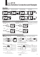
%XAMPLEOF!.$3ERIESAND/20ARALLEL#ONNECTION
%XAMPLEOF#ONNECTIONWITH0,#0ROGRAMMABLE,OGIC#ONTROLLER
Indicator
protection
circuit,
etc.
Brown
Blue
Load
Indicator
protection
circuit,
etc.
Brown
Blue
Load
"ASIC7IRING
3OLIDSTATEWIRE.0. WIRE3OLIDSTATE3OLIDSTATEWIRE0.0 WIRE2EED
Connect according to the applicable PLC
input specifications, as the connection
method will vary depending on the PLC
input specifications.
Black
Brown
Blue
Black
Brown
Blue
Blue
Brown Blue
Brown
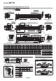
sWIRE
/2CONNECTIONFOR.0.OUTPUT
WIREWITHSWITCH!.$CONNECTION WIREWITHSWITCH/2CONNECTION
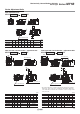
Load voltage at ON = Power supply voltage – Residual voltage x 2 pcs.
= 24 V – 4 V x 2 pcs.
= 16 V
Example: Power supply voltage 24 VDC
Auto switch internal voltage drop 4 V
Load voltage at OFF = Leakage current x 2 pcs. x Load impedance
= 1 mA x 2 pcs. x 3 kΩ
= 6 V
Example: Load impedance 3 k
Ω
Auto switch leakage current 1 mA
Auto switch 1
Auto switch 2
Load
Brown
Black
Blue
Brown
Black
Blue
Auto switch 1
Brown
Auto switch 2
Black
Blue
Relay
Relay
Brown
Black
Blue
Load
Relay
contact
Auto switch 1
Auto switch 2
Brown
Blue
Brown
Blue
Load
Auto switch 1
Auto switch 2
Brown
Blue
Brown
Blue
Load
!.$CONNECTIONFOR.0.OUTPUT
5SINGRELAYS
Auto switch 1
Brown
Auto switch 2
Black
Blue
Load
Brown
Black
Blue
!.$CONNECTIONFOR.0.OUTPUT
0ERFORMEDWITHAUTOSWITCHESONLY
The indicator lights will light up when both
of the auto switches are in the ON state.
When two auto switches
are connected in series,
malfunction may occur
because the load voltage
will decrease in the ON
state.
The indicator lights will
light up when both of the
auto switches are in the
ON state.
(Solid state)
When two auto switches
are connected in parallel,
malfunction may occur
because the load voltage
will increase in the OFF
state.
(Reed)
Because there is no
leakage current, the load
voltage will not increase
in the OFF state.
However, depending on
the number of auto
switches in the ON state,
the indicator lights may
sometimes grow dim or
not light up, due to the
dispersion and reduction
of the current flowing to
the auto switches.
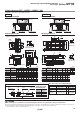
sWIRE
Series MY1B
!UTO3WITCHES#ONNECTIONAND%XAMPLE
15