
Datasheet


HSB + Stroke B SA + Stroke A
ZZ + Stroke (A + B)
C port
∗ Needle
position
for D port
D port
W
θ
W
θ
B port
C port
GC
D port
Note)
∗
WD
A port
GD
10
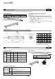
Dual Stroke Cylinder/Single Rod Type
-XC11
Symbol
Two cylinders can be integrated by connecting them in line, and the cylinder stroke can be controlled in two stages in both directions.
Series Description Model Action Note
CG1-Z
Standard type CG1
Double acting, Single rod
Applicable Series
Dual stroke cylinder/single rod type
How to Order
Mounting style Bore size Suffi xStroke A Stroke B-A
XC11CG1
Type
Z
Precautions
1. Do not supply air until the cylinder is fi xed with the attached bolt.
2. If air is supplied without securing the cylinder, the cylinder could lurch,
posing the risk of bodily injury or damage to the peripheral equipment.
Caution
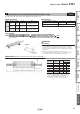
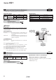
Dimensions
(Dimensions other than below are the same as standard type.)
Specifi cations: Same as standard type
∗ Please contact SMC for each manufacturable stroke length.
58
Made to Order
Series CG1
ACB
B Stroke A Stroke
A
AC
AC
B Stroke A Stroke
CB
A Stroke
B
B
B-A Stroke
ACB
B Stroke A Stroke
AC
B
W
A Stroke
W
ACB
B Stroke A Stroke
ACB
B Stroke A Stroke
A
CB
A Stroke
C
B A
B Stroke
∗ ( ): With air cushion
Note) If the A stroke exceeds 301 mm. (ø40 to ø63)
Note) D port style Type N: Rubber bumper, Plug with fi xed orifi ce;
Type A: Air cushion, element non-installation
(Release to atmospheric pressure)
[mm]
A Stroke Range
Bore size Stroke range
ø20 Up to 200 mm
ø25, ø32 Up to 300 mm
Bore
size
GC GD H SA SB Wθ ZZ
Air
cushion
Long
stroke
WD SA ZZ
20
21 9 35 48 87 30° 172 5 − −
25
21 (21.5) 9 (8.5) 40 48 87 30° 177 6.5 − −
32
23 9 40 50 91 30° 183 5 − −
40
25 9 50 56 100 20° 208 5 65 217
50
29 13 58 63 118 20° 241 9 75 253
63
28 12 58 64 117 20° 241 8 76 253
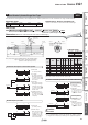
B stroke operation
1) Initial state
(0 stroke position)
A stroke operation
Functional description of dual stroke cylinder
Double output is possible.
A stroke or B stroke operation can be made individually.
1) Initial state
(0 stroke position)
1) Initial state
(0 stroke position)
1) Initial state
(0 stroke position)
Note)
2) 1st stage
(A stroke operation)
When the air pressure
is supplied from the
port, the rod operates
the A
stroke.
3) 2nd stage
(B-A stroke operation)
Following the 1st stage,
when the air pressure
is supplied from the
port, the rod operates
the B-A stroke.
4) Cylinder retraction
When the air pressure
is supplied from the
port, the rod retracts
completely.
2) Double output
When the air pressure
is supplied to the
and ports at the
same time, the double
output can be obtained
in the A stroke range.
2) Operation
When the air pressure
is supplied from
the port, the rod
operates the A stroke.
2) Operation
When the air pressure
is supplied from
the port, the rod
operates the B stroke.
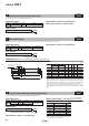
CG1CG1WCG1CG1KCG1KWCG1R
StandardNon-rotating RodDirect Mount
Double Acting, Single RodDouble Acting, Double Rod
Single Acting, Spring Return/Extend
Double Acting, Single RodDouble Acting, Double RodDouble Acting, Single Rod
Auto SwitchMade to Order