Doc. No.
Contents ・・・P 3、4 Safety Instructions 1. Specifications ・・・P 5 2. Port size and flow characteristics ・・・P 5 3. How to Order ・・・P 5 4. Configuration symbol ・・・P 6 5. Piping method ・・・P 7,8 6. Frequency adjustment ・・・P 9,10 7. Mounting ・・・P 11 8. Environment ・・・P 11 9. Lubricant oil ・・・P 11 ・・・P 11 10.
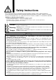
Safety Instructions These safety instructions are intended to prevent hazardous situations and/or equipment damage. These instructions indicate the level of potential hazard with the labels of “Caution,” “Warning” or “Danger.” They are all important notes for safety and must be followed in addition to International Standards (ISO/IEC)*1) , and other safety regulations. *1) ISO 4414: Pneumatic fluid power -- General rules relating to systems.
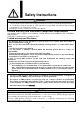
Safety Instructions Caution The product is provided for use in manufacturing industries. The product herein described is basically provided for peaceful use in manufacturing industries. If considering using the product in other industries, consult SMC beforehand and exchange specifications or a contract if necessary. If anything is unclear, contact your nearest sales branch.
1. Specifications Valve construction Fluid Max. operating pressure External pilot air pressure Metal seal Air 1.0MPa 0.2 to 1.0MPa (External pilot type) 1 to 5Hz (internal pilot type) Frequency adjustment range 1 to 8Hz (external pilot type) Proof pressure 1.5MPa Ambient and fluid temperature -20 to +60 oC Lubrication No Enclosure rating IP65 equivalent Weight About 1,400g ※Use an External pilot pressure higher than IN port pressure. 2.
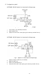
4. Configuration symbol AXTS040*-2(B)-X2 Symbol for internal pilot fluid passage Fig.1 Symbol for internal pilot fluid passage. ・ ・ ・ 1(P) Port:IN Port SUP.Air(for air blow) 4(A) Port:OUT Port 3(R2) Port: Released to atmosphere (pilot exhaust port with silencer) AXTS040*-3(B)-X2 Symbol for internal pilot fluid passage Fig.2 ・ ・ ・ ・ Symbol for external pilot fluid passage. 3(R2) port: IN Port SUP.
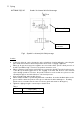
5. Piping AXTS040*-2(B)-X2 Symbol for internal pilot fluid passage OUT Port 4(A) AXTS040*-2(B)-X2 Air blow 2-port valve IN Fig.3 Symbol for internal pilot fluid passage. Caution ・ ・ ・ ・ ・ ・ Continuous blow air can be changed to pulse air without electrical wiring by connecting the pulse blow valve between air blow 2 port valve and nozzle of existing equipment. When an air gun and a pressure regulator are connected to OUT port, the back pressure of the OUT port will be high.
AXTS040*-3(B)-X2 External pilot type OUT Port 2(B) OUT Port 2(B) port AXTS040*-3(B)-X2 Pilot air Control valve Pilot air Control valve X Port Fig.4 Piping for External pilot fluid passage 1 Fig.5 IN Piping for External pilot fluid passage 2 Caution ・ The description of the sub plate and piping port do not match. Be careful with the piping port. ・ For external pilot type, pulse air is only generated while pilot air is supplied.
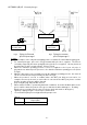
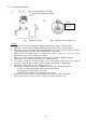
6. Frequency adjustment Scale (0 to 8) Fig.6 Adjustment needle Fig.7 Adjustment needle Expansion Caution ・ ON time is shortened by rotating the ON time adjustment needle counterclockwise. ・ OFF time is shortened by rotating the OFF time adjustment needle counterclockwise. ・ Refer to the scale as a guideline for resetting. ON time ratio does not become 50% even when setting the adjustment needle for ON and OFF at the same value. ・ Small amount of leakage exists even when the needle is fully close.
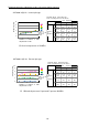
Relation between the adjustment needle scale and operation frequency AXTS040*-2(B)-X2 Internal pilot type AXTS040*-2B-X2 Internal pilot valve AXTS040*-2(B)-X2 内部パイロットタイプ Ratio of operating frequency and ON time 作動周波数とON時間の割合 OFF調整[回転] OFF adjustment Frequency 周波数[Hz] [Hz] 10 7 5 3 1 8 6 2 0 0 2 4 6 3 5 7 2.1 Hz 2.6 Hz 3.1 Hz 3.8 Hz 1 ON adjustme Number of OFF調整用 ON調整 rotation of ON nt[回転] ニードル [Rotation] adjustment 回転数 needle 4 1 8 31% 64% 74% 73% 2.6 Hz 3.0 Hz 3.4 Hz 4.
7. Mounting Before connecting the valve, flush the piping of the upstream (supply pressure port side) and downstream (control equipment port side) to eliminate particles in the piping and foreign matter and scales generated during piping. 8. Environment Please contact SMC if the product is used where corrosive gas, chemicals and their solutions, water vapor, or seawater droplets exist, or temperature exceeds 50oC, or vibration occurs. 9.
Revision history A:Modify items in graph B:Change symbol https://www.smcworld.com This manual is subject to change without prior notice.