
Datasheet


67
Series AL10-A to AL60-A
0.1
0.08
0.06
0.04
0.02
0
0
1000 2000 3000 4000
P
1
=0.1 MPa
P
1
=0.3 MPa
P
1
=0.5 MPa
P
1
=0.7 MPa
Pressure drop [MPa]
Flow rate L/min
(
ANR
)
0.08
0.1
0.06
0.04
0.02
0
0
2000 4000 6000
P
1
=0.5 MPa
P
1
=0.1 MPa
P
1
=0.7 MPa
P
1
=0.3 MPa
Pressure drop [MPa]
Flow rate L/min
(
ANR
)
0.08
0.1
0.06
0.04
0.02
0
0
2000 4000 6000 8000
P
1
=0.1 MPa
P
1
=0.3 MPa
P
1
=0.5 MPa
P1
=0.7 MPa
Pressure drop [MPa]
Flow rate L/min
(
ANR
)
0.1
0.08
0.06
0.04
0.02
0
0
2000 4000 6000 8000
P
1
=0.1 MPa
P
1
=0.3 MPa
P
1
=0.5 MPa
P
1
=0.7 MPa
Pressure drop [MPa]
Flow rate L/min
(
ANR
)
150001000050000
P
1
=0.1 MPa
P
1
=0.7 MPa
P
1
=0.5 MPa
P
1
=0.3 MPa
Pressure drop [MPa]
Flow rate L/min
(
ANR
)
0.08
0.1
0.06
0.04
0.02
0
0
0.02
0.04
0.06
0.08
0.1
0 50 100 150 200
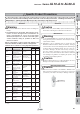
Conditions: P1 = 0.5 MPa
Needle: One side fully open
Pressure drop [MPa]
Flow rate L/min
(
ANR
)
Needle fully open
Open 0.5 turn
Open 1.0 turn
Open 1.5 turns
Open 2.0 turns
A portion of the air introduced from the IN side pressurizes the lubricant inside the bowl. The remainder
of the air passes through the needle o, and fl ows to the OUT side. The differential pressure between the
inside of the bowl and the inside of the sight dome w, causes the lubricant inside the bowl into the oil
passage !0. The lubricant drips from the dripping tube !1, and lubricates the OUT side. The amount of
lubricant is adjusted by the needle o on the front face. Turning the needle clockwise increases the
amount of the lubricant, and turning it counterclockwise until fully open shuts off the lubricant. The needle
on the side that is not used should be left fully open.
Needle
Section AA’
AL20-A
Rc1/4
AL30-A
Rc3/8
AL40-A
Rc1/2
AL40-06-A
Rc3/4
AL50-A
Rc1
AL10-A
M5
Flow-rate Characteristics
(Representative values)
Working Principle: AL10 Type
0.1
0.08
0.06
0.04
0.02
0
150001000050000
P
1
=0.1 MPa
P
1
=0.7 MPa
P
1
=0.5 MPa
P
1
=0.3 MPa
Pressure drop [MPa]
Flow rate L/min
(
ANR
)
AL60-A
Rc1